Photosensitive Drums for Laser Printers

A technology for laser printers and photosensitive drums, applied in optics, electrical recording technology using charge graphics, equipment using electrical recording technology using charge graphics, etc., can solve problems such as inability to effectively transmit torque, achieve effective transmission, and avoid mutual misalignment Effect

Active Publication Date: 2015-12-23
PRINT RITE UNICORN IMAGE PROD CO LTD
View PDF6 Cites 0 Cited by
  • Summary
  • Abstract
  • Description
  • Claims
  • Application Information

AI Technical Summary

Problems solved by technology

[0008] In view of the problem that the torque cannot be effectively transmitted between the photosensitive drum and the laser printer due to the inaccurate alignment of the drive head and the force bearing block, the purpose of the present invention is to provide a photosensitive drum for the laser printer

Method used


Image

  • Photosensitive Drums for Laser Printers
  • Photosensitive Drums for Laser Printers
  • Photosensitive Drums for Laser Printers

Examples


Embodiment Construction

[0019] The photosensitive drum of the present invention will be described in detail below with reference to the accompanying drawings.

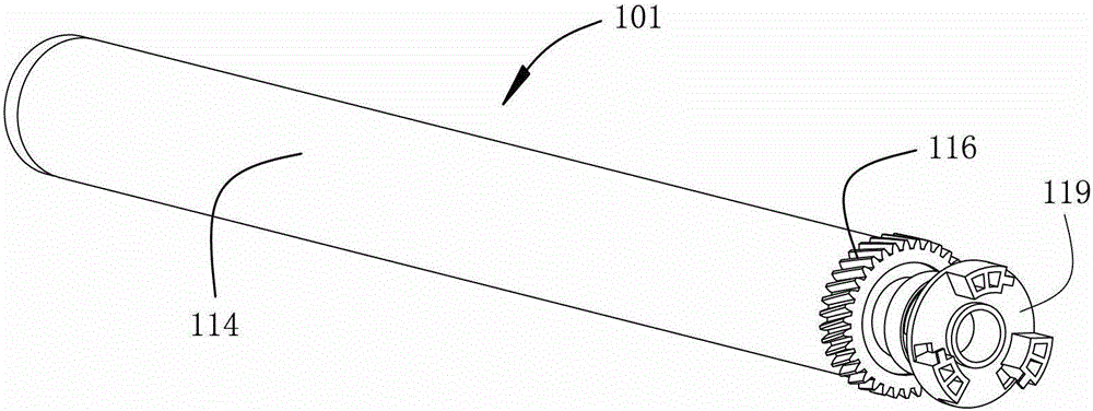
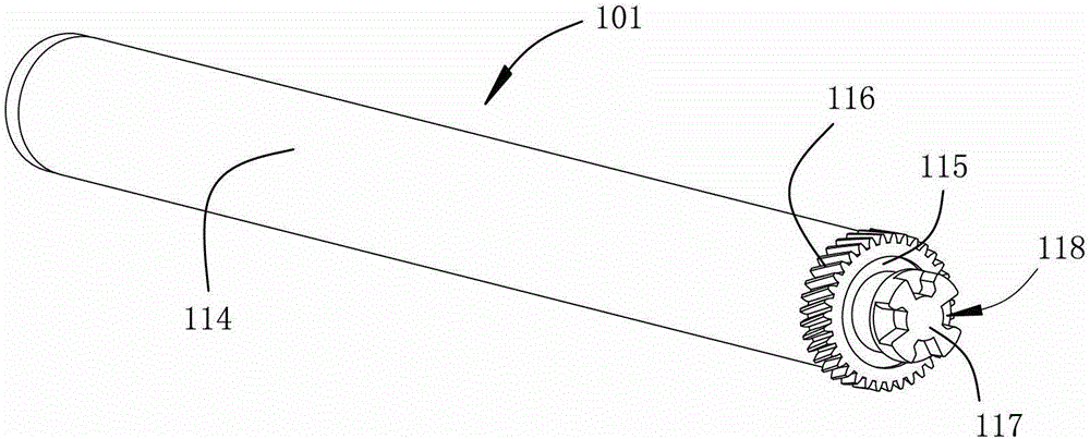
[0020] Figure 5 , 7 , respectively show perspective views of the photosensitive drum of the present invention and its docking with the drive head of the existing laser printer from different perspective angles.

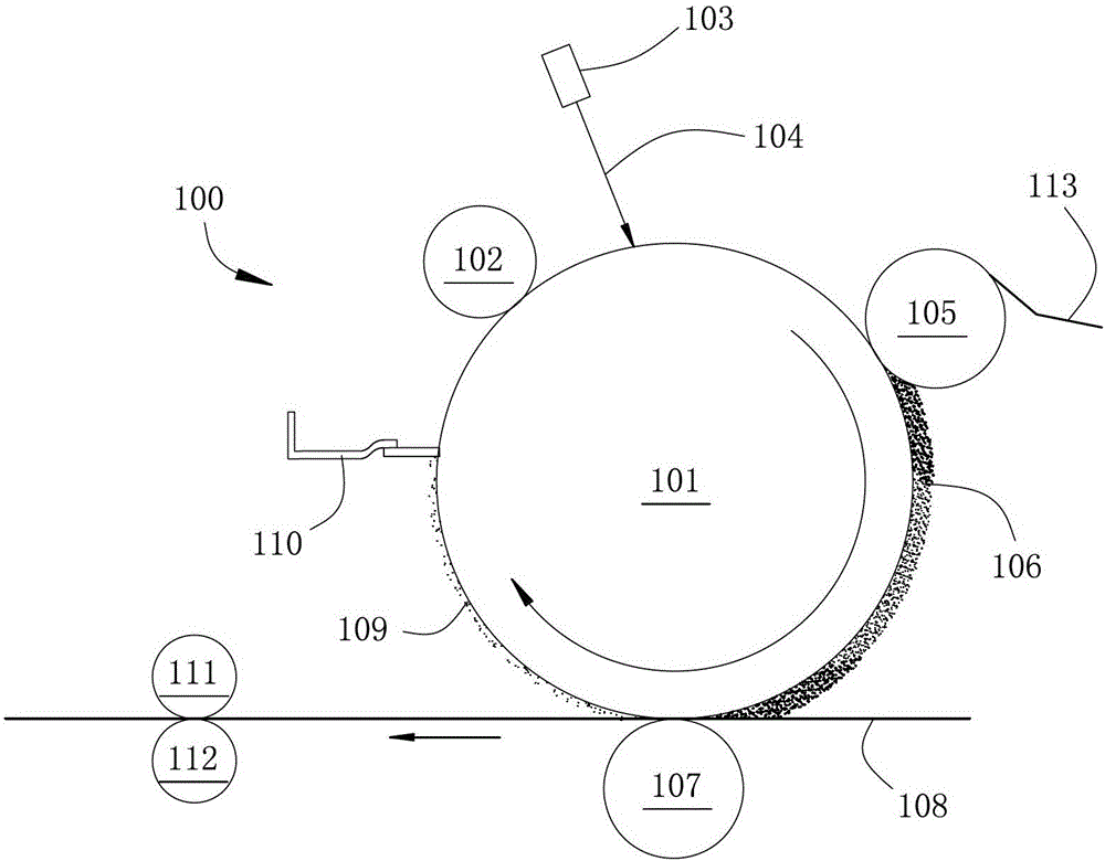
[0021] The main structure of the photosensitive drum used in the laser printer of the present invention is basically the same as the prior art in the similar field. Those skilled in the art can refer to the relevant technical materials of the prior art in the similar field and combine the introduction of the background technology part of the specification to know the laser printer of the present invention. The basic structure of the photosensitive drum. In view of this, the reference numerals of the components involved in the description of the specific embodiments of the photosensitive drum for laser printers of the present inven...


PUM


Abstract

A photosensitive drum (101) for a laser printer comprises a photosensitive component (114) and a transmission component (115). The transmission component (115) is fixed on one side of the photosensitive component (114) along the lengthwise direction thereof. One end of the transmission component (115) along the length direction of the photosensitive component (114) that faces away from the photosensitive component (114) is provided with a cylindrical stressed block (117). An external end wall of the stressed block (117) along the axis direction thereof that faces away from the photosensitive component (114) is provided with a blind hole (121) recessed inwardly along the axis direction thereof. The blind hole (121) is provided with a continuous hole wall on an axial cross section of the stressed block (117). The number of blind holes (121) is four. On the axial cross section of the stressed block (117), four blind holes (121) are symmetrically distributed relative to the radial centre of the stressed block (117). The stressed block (117) of the photosensitive drum (101) and a driving head (119) of the laser printer are positioned to be aligned accurately, thus stably acquiring the required rotational driving force from the laser printer.

Description

technical field [0001] The present invention relates to a photosensitive drum as a component of a laser printer. The photosensitive drum is composed of a photosensitive part and a transmission part. Background technique [0002] The imaging process of the laser printer with the process box 100 as the basic core is, see figure 1 , the surface of the photosensitive drum 101 is uniformly charged by the charging roller 102 . The laser scanner 103 emits a modulated laser beam 104 containing image information to the outer cylindrical surface of the photosensitive drum 101, and after being irradiated by the laser beam 104, an electrostatic charge distribution map with differences in distribution is formed on the cylindrical surface of the photosensitive drum 101, also That is, the electrostatic latent image corresponding to the image to be reproduced. Afterwards, the developer such as carbon powder 106 transmitted from the developing roller 105 turns to be adsorbed on the cylind...

Claims


Application Information

Patent Timeline
Patent Type & Authority Patents(China)
IPC IPC(8): G03G15/00
CPCG03G15/757
Inventor 杨晓锋赖亚勇
Owner PRINT RITE UNICORN IMAGE PROD CO LTD
Why Eureka
Try Eureka