
Autoinjectors

An automatic injection and syringe technology, applied in the direction of automatic injectors, syringes, ampoule syringes, etc., can solve the problems of expensive manufacturing and assembly

Inactive Publication Date: 2013-09-18
OWEN MUMFORD
View PDF5 Cites 5 Cited by
  • Summary
  • Abstract
  • Description
  • Claims
  • Application Information

AI Technical Summary

Problems solved by technology

This is expensive in terms of design and testing etc. as well as manufacturing and assembly

Method used


Image

  • Autoinjectors
  • Autoinjectors
  • Autoinjectors

Examples


Embodiment Construction

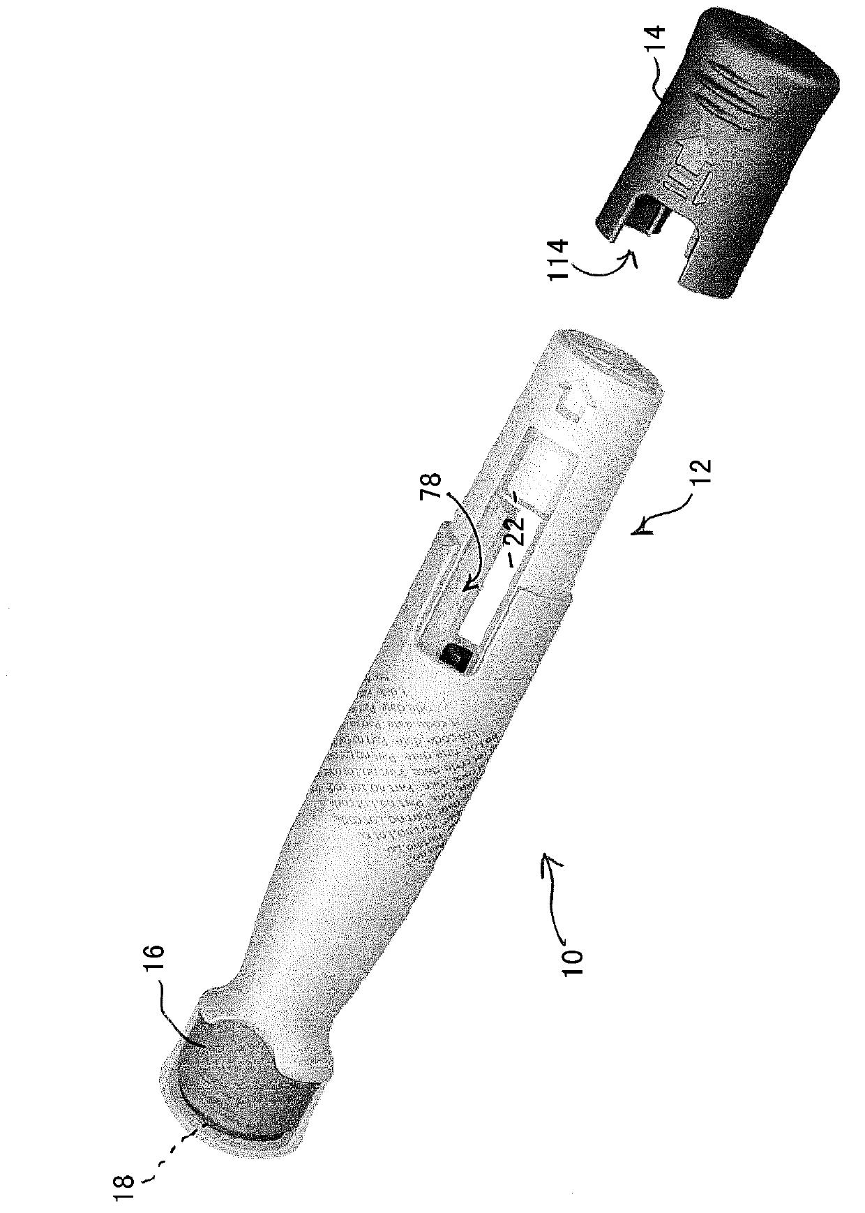
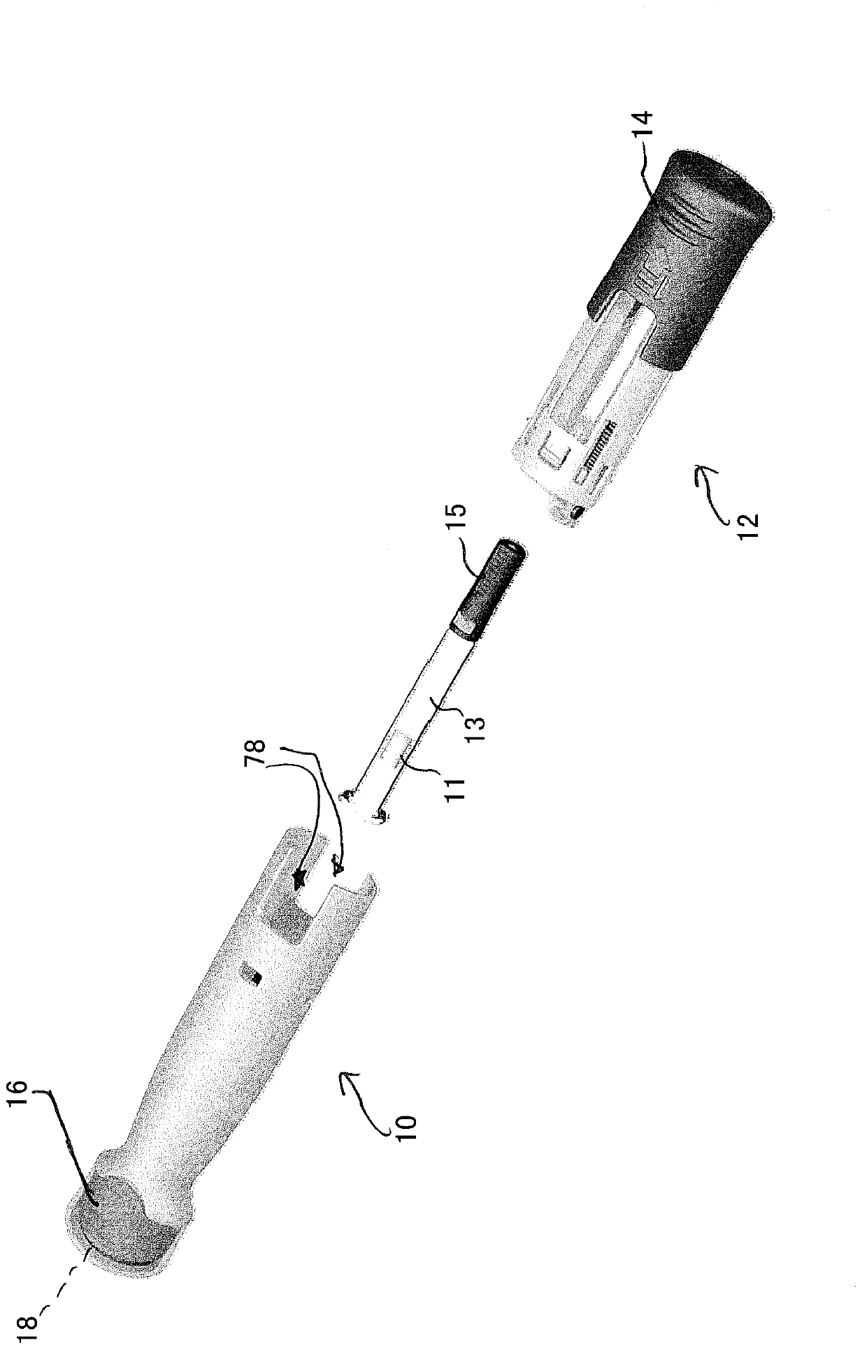
[0034] Embodiments of the automatic injection device described below and shown in the accompanying drawings are designed to automatically inject a selected dose of a medicament when given an injection position and triggering the injection. First refer to figure 1 and 2 , the automatic injection device comprises a rear assembly 10 accommodating a drive mechanism and a front assembly 12 for accommodating a syringe 13 with a medicament. The front and rear assemblies snap fit together during manufacture. On the front end of the device is a removable cover 14 which also serves as a needle shield removal device, as described below. At the rear end of the rear assembly is a rear cover 16 which includes a safety pin which prevents abnormal or accidental triggering of the injection from the drive mechanism and which also covers a trigger injection button 18 .

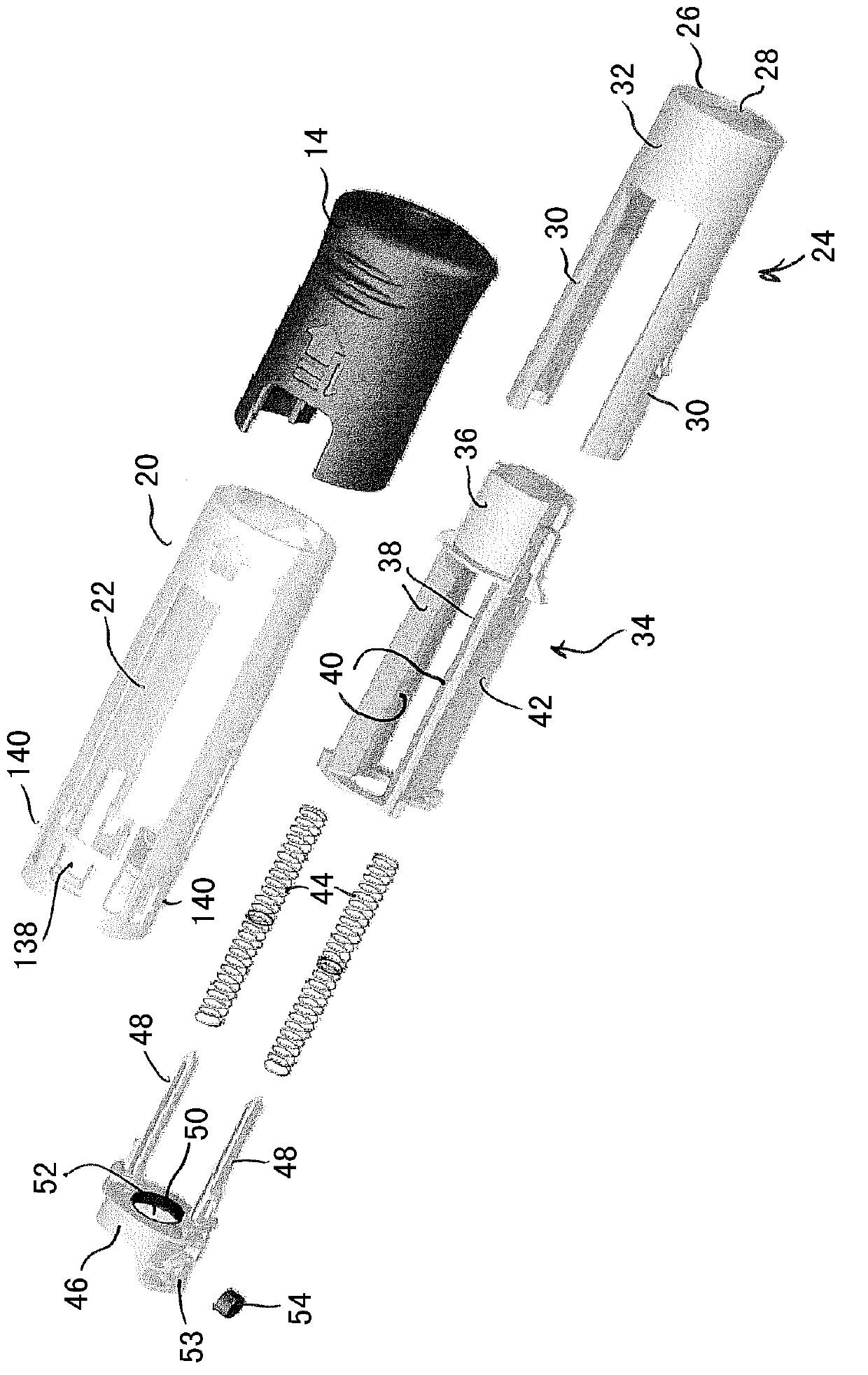
[0035] now refer to image 3 , the front assembly 12 includes an outer body housing 20 of generally transparent plastic ma...


PUM


Abstract

An autoinjector comprises a rear body assembly (10) connected to a front body assembly, wherein said rear body assembly (10) contains a drive mechanism (60) and said front body assembly contains a syringe (13) or cartridge with a needle at its forward end. The front body assembly includes a viewing window (22) through which at least part of the contents of the syringe (13) or cartridge are visible, a removable cap (14) is fitted to the forward end of the front body assembly, and the rear body assembly and the removable cap have respective aligned cut-away regions together defining a frame for said viewing window. Also disclosed is a modular scheme which uses a common platform for the provision of a range of autoinjectors of different fill volumes, with only the length of the plunger (60), and the axial extent of the cut out varying between different versions.

Description

technical field [0001] The present invention relates to automatic injection devices. Background technique [0002] Autoinjection devices are generally used to allow self-administration, particularly but not exclusively, in situations where periodic continuation of therapy is required. In these cases, the dosage volume of the drug may vary depending on the nature of the condition being treated, stage of treatment, patient weight, and the like. Similarity in operation and appearance of devices and sharing of components between multiple devices is desirable for a number of reasons. In practice, however, the need to provide different dose volumes often requires significant redesign of the automatic injection device. This is expensive in terms of design and testing etc. as well as manufacturing and assembly. Contents of the invention [0003] Therefore, the present invention contemplates an automatic injection device which, in a particular example, requires only two parts to...

Claims


Application Information

Patent Timeline
IPC IPC(8): A61M5/28A61M5/20
CPCA61M5/2033A61M5/31533A61M5/3157A61M5/3204A61M5/326A61M2005/206A61M2005/2073A61M2005/2418A61M2005/3247A61M2205/581A61M2207/00Y10T29/53Y10T29/49826A61M5/31A61M5/20
Inventor 罗伯特·沃曾克罗夫特
Owner OWEN MUMFORD
Features
  • Generate Ideas
  • Intellectual Property
  • Life Sciences
  • Materials
  • Tech Scout
  • Unparalleled Data Quality
  • Higher Quality Content
  • 60% Fewer Hallucinations
Learn More