The Method of Reservoir Exploitation by Nanometer Magnetic Fluid Displacement and Its Well Pattern Structure
A nano-magnetic fluid, well-displacement technology, which is applied in the fields of fluid production, earth-moving drilling, wellbore/well components, etc., can solve the problems of effective production, low oil and steam, and limited water-flooding recovery effect.
- Summary
- Abstract
- Description
- Claims
- Application Information
AI Technical Summary
Problems solved by technology
Method used
Image
Examples
Embodiment 1
[0048] This embodiment provides a method for nano-magnetic fluid displacement to recover oil reservoirs. Under the conditions of oil layers, the viscosity of degassed crude oil in this oil reservoir is 10 centipoise, and the effective permeability is 15mD. It belongs to conventional low-permeability thin oil reservoirs. The target The effective thickness of the oil layer 9 is 20m, and the target oil layer refers to a certain independent oil layer developed in this embodiment or several independent oil layers developed in general when the oil field production area contains one or several independent oil layers; Water rock, the oil reservoir is now exploited by nano-magnetic fluid displacement.
[0049] step one:
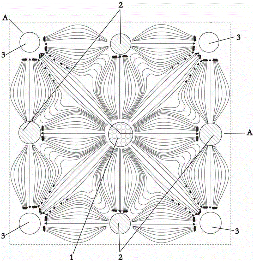
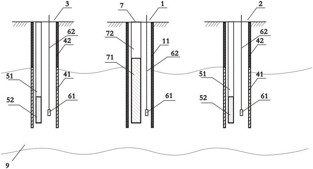
[0050] A well pattern is set in the reservoir area; the well pattern includes at least one displacement well group 100; as figure 1 As shown, the displacement well group 100 includes an injection well 1, and on a square centered on the injection well 1, four side wel...
Embodiment 2
[0068] The principle of this embodiment is basically the same as that of Embodiment 1. The difference is that the viscosity of the degassed crude oil of the heavy oil in the selected reservoir is 1000 centipoise under the conditions of the oil reservoir, which belongs to the heavy oil reservoir. The effective thickness of the target oil layer 9 is 30 m. The rock is oil-loving rock; the oil reservoir is exploited by nano-magnetic fluid flooding.
[0069] step one:
[0070] A well pattern is set in the reservoir area; the well pattern includes at least one displacement well group 100; as figure 1 As shown, the displacement well group 100 includes an injection well 1, and on a square centered on the injection well 1, four side wells 2 and four corner wells 3 are set, and the side wells 2 and corner wells 3 are for production Well, a square anti-nine-point displacement well group is formed by the above-mentioned injection well 1, side well 2 and corner well 3;
[0071]The above-...
PUM
 Abstract
Description
Claims
Application Information
 - R&D
- Intellectual Property
- Life Sciences
- Materials
- Tech Scout
- Unparalleled Data Quality
- Higher Quality Content
- 60% Fewer Hallucinations
Browse by: Latest US Patents, China's latest patents, Technical Efficacy Thesaurus, Application Domain, Technology Topic, Popular Technical Reports.
© 2025 PatSnap. All rights reserved.Legal|Privacy policy|Modern Slavery Act Transparency Statement|Sitemap|About US| Contact US: help@patsnap.com


