Method and device for adjusting misalignment of shells of mold for fan blade during assembling

The technology of an adjusting device and an adjusting method is applied in the field of mold clamping and dislocation adjustment of fan blade molds, which can solve problems such as non-compliance with process requirements, inaccurate adjustment of dislocation, and personal safety hazards of operating workers, so as to solve the problem of mold dislocation and facilitate assembly. The effect of mold misalignment adjustment and reduction of construction safety risk

Active Publication Date: 2013-10-16
广东明阳新能源材料科技有限公司
View PDF3 Cites 2 Cited by
  • Summary
  • Abstract
  • Description
  • Claims
  • Application Information

AI Technical Summary

Problems solved by technology

During the installation and debugging of the blade mold, because the mold is too long, the windward side and the leeward side of the mold are prone to misalignment; at the same time, because the mold is long and heavy, the traditional method is to pull the windward side with a steel wire rope or a sling E. This method It is very dangerous and will cause harm to the personal safety of the operators; in addition, because this method cannot be accurately positioned, the force is sometimes large and sometimes small, so the misalignment cannot be accurately adjusted, and the probability of achieving the expected effect is very low
The misalignment seriously affects the cavity profile of the mold, and finally affects the produced blades, which do not meet the process requirements
Therefore, the problem of misalignment of the mold after installation has become an urgent problem to be solved in the industry.

Method used


Image

  • Method and device for adjusting misalignment of shells of mold for fan blade during assembling
  • Method and device for adjusting misalignment of shells of mold for fan blade during assembling
  • Method and device for adjusting misalignment of shells of mold for fan blade during assembling

Examples


Embodiment Construction

[0025] The present invention will be further described in detail below in conjunction with the embodiments and the accompanying drawings, but the embodiments of the present invention are not limited thereto.

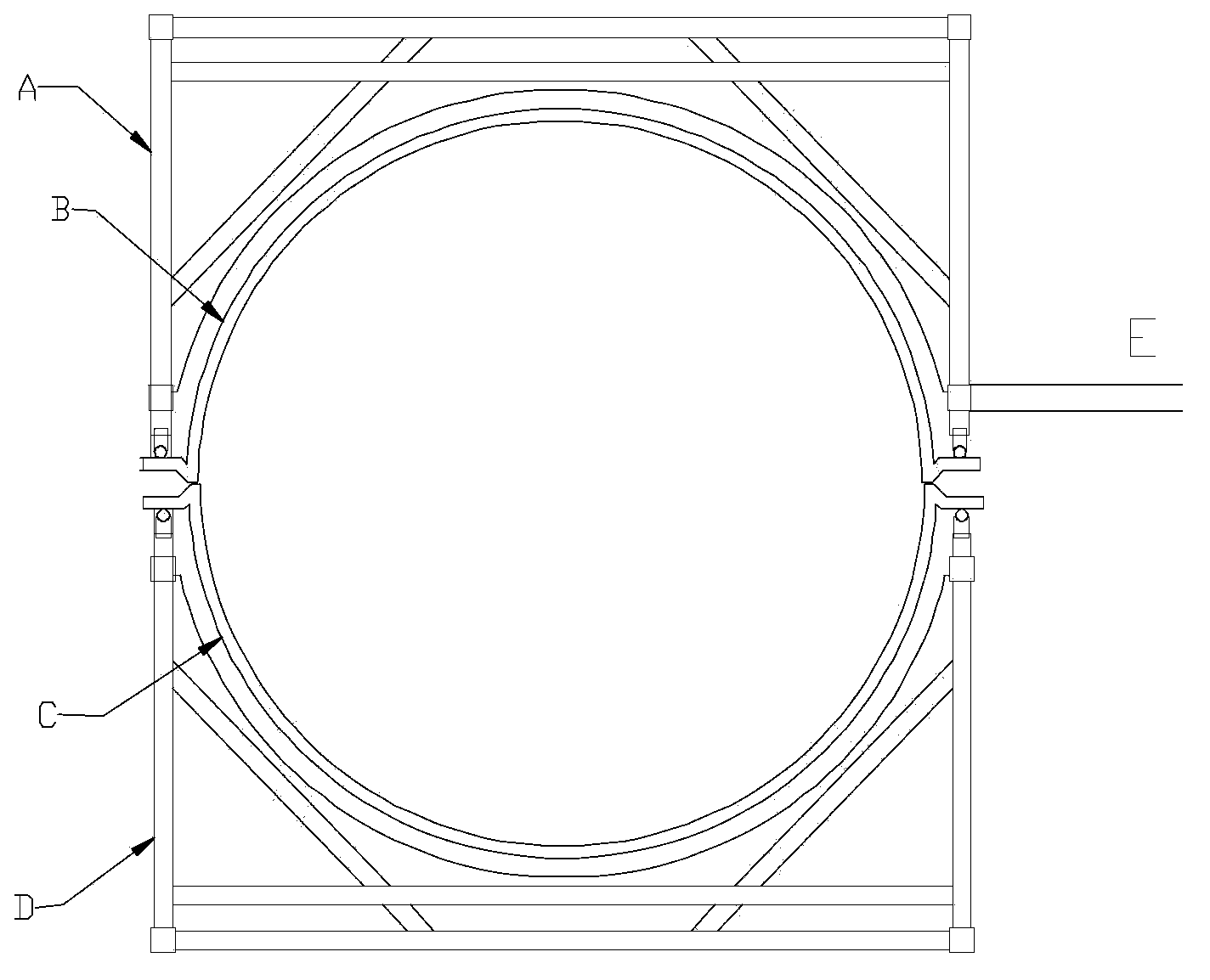
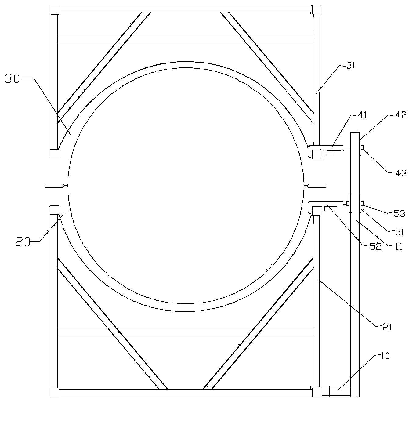
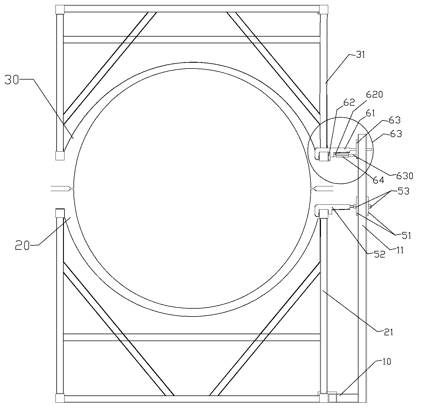
[0026] The blade mold includes an upper mold shell 30 and a lower mold shell 20 , the upper mold shell 30 is fixed on the upper mold steel frame 31 , and the lower mold shell 20 is fixed on the lower mold steel frame 21 . The lower mold shell 20 and the lower mold steel frame 21 are placed flat on the ground or on the table, the upper mold shell 30 and the upper mold steel frame 31 are placed flat on the lower mold shell 20 and the lower mold steel frame 21 by a crane, and the upper mold shell 30 After being docked with the lower formwork 20, a hollow blade cavity is formed.

[0027] A method for adjusting mold clamping and misalignment of fan blade molds. The adjustment method is as follows: a detachable adjustment device is installed on the steel frame of the lower mol...


PUM


Abstract

The invention discloses a method for adjusting the misalignment of shells of a mold for fan blades during assembling. The mold comprises an upper shell and a lower shell, wherein the upper shell is fixed on an upper mold steel frame, and the lower shell is fixed on a lower mold steel frame; the upper shell and the upper mold steel frame are put on the lower shell and the lower mold steel frame respectively; the upper shell and the lower shell are abutted together to form a hollow fan-blade mold cavity. The method comprises the following steps of: arranging a detachable adjusting device on the lower mold steel frame, wherein the adjusting device is provided with an adjusting nut; rotating the adjusting nut so that the adjusting nut pulls the upper mold steel frame and the upper shell to move transversely together through a screw rod to align the upper shell to the lower shell; locking and fixing the upper mold steel frame and the lower mold steel frame by a group of mold locking and positioning devices; detaching the adjusting device. The invention aims to provide the method and the device for accurately and conveniently adjusting the misalignment of the shells of the mold for the fan blades during assembling.

Description

technical field [0001] The invention relates to a wind power blade mold used for making wind power generator blades, in particular to a method and device for adjusting mold clamping and misalignment of a wind blade mold. Background technique [0002] As the power of wind turbines in the wind power industry increases, the wind power blades become longer and larger, and the wind power blade molds also become longer and larger. Existing blade molds generally include an upper mold shell B (windward side) and a lower mold shell C (leeward side), the upper mold shell B is fixed on the upper mold steel frame A, and the lower mold shell C is fixed on the lower mold steel frame D (see figure 1 ), the upper mold shell and the upper mold steel frame are placed on the lower mold shell and the lower mold steel frame, and the upper mold shell and the lower mold shell are butted to form a hollow blade cavity. During the installation and debugging of the blade mold, because the mold is too...

Claims


Application Information

Patent Timeline
Patent Type & Authority Applications(China)
IPC IPC(8): B29C33/30
Inventor 张建红林雄
Owner 广东明阳新能源材料科技有限公司
Why Eureka
Try Eureka