
Head box for a paper machine

A headbox, paper machine technology, applied in paper machine, paper machine, wet end of paper machine, etc., can solve the problems of increased wear, complexity and large pressure drop of turbulence generators

Inactive Publication Date: 2013-11-06
BASALAN
View PDF3 Cites 2 Cited by
  • Summary
  • Abstract
  • Description
  • Claims
  • Application Information

AI Technical Summary

Problems solved by technology

However, this solution is also very complex due to the need for multiple slides that must be positionally constrained within a narrow range
This highly asymmetric structure results in a large pressure drop across the turbulence generator and makes the turbulence generator susceptible to increased wear

Method used


Image

  • Head box for a paper machine
  • Head box for a paper machine

Examples


Embodiment Construction

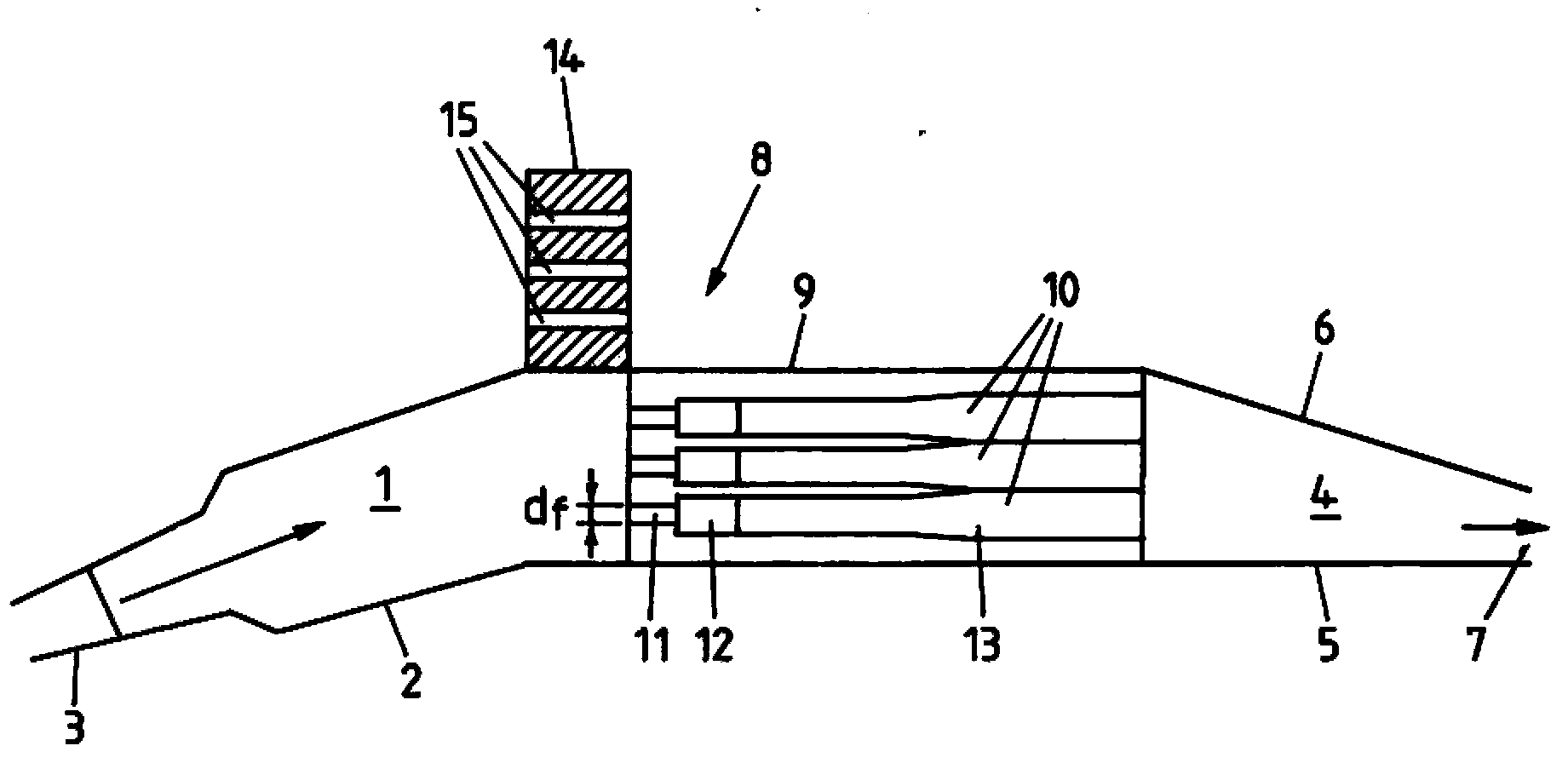
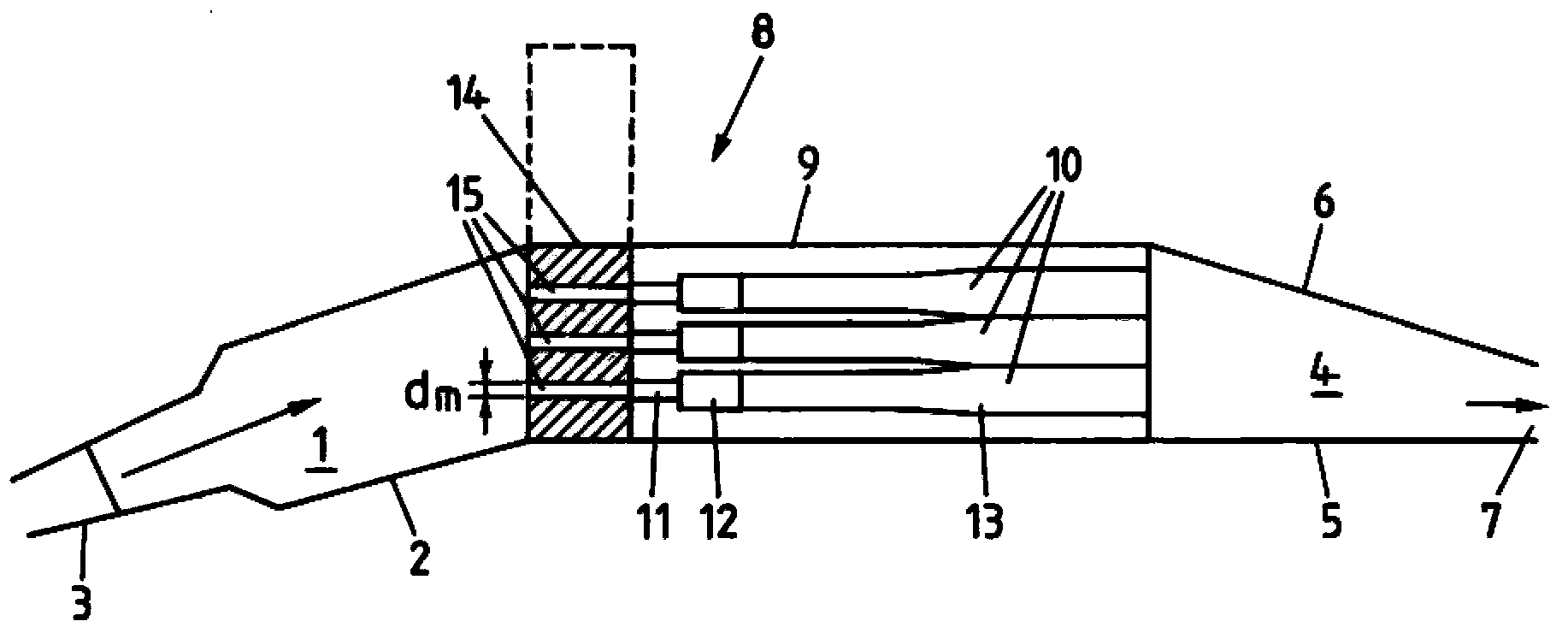
[0010] The headbox distributes the pulp from the central distributor on the conveyor belt of the paper machine. The direction of pulp flow is indicated by arrows. The headbox comprises an inflow chamber 1 at the upstream end. The inflow chamber 1 is surrounded by a housing 2 with a plurality of connectors 3 arranged side by side. On each connector 3 is connected an elastic feed pipe protruding from the central distributor. All feed tubes have the same length. On the downstream end on the opposite side, the headbox comprises an outflow chamber 4 formed between a bottom plate 5 and a cover plate 6 and having a constant cross-section in a transverse direction perpendicular to the flow direction. The volume of the outflow chamber 4 decreases in flow direction so that it ends in a horizontal outflow chute 7 arranged above the conveyor belt.

[0011] A turbulence generator 8 is arranged between the inflow chamber 1 and the outflow chamber 4 . The turbulence generator comprises ...


PUM

PropertyMeasurementUnit
Lengthaaaaaaaaaa

Abstract

A turbulence generator (8) consists of a fixed part (9) containing fixed sections (10) of an array of parallel ducts, and a movable part (14) with, for each duct, a movable section (15) with a diameter smaller than the minimal diameter of the adjacent fixed section (10). If the overall rate of the stock flow is large a maximal flow velocity sufficient for producing a required degree of turbulence can be reached with the fixed part (9) alone and the movable part (14) is removed from the flow path. Where the flow rate is too small for that the movable part (14) is placed in the flow path and the minimal overall cross section area reduced. This results in an increase of the maximal velocity of the flow which is then again sufficient to engender turbulence of the desired degree and intensity. In this way two different ranges of paper which require different ranges of flow rates can be produced.

Description

technical field [0001] The invention relates to the headbox of a paper machine. This type of headbox is used to distribute the pulp on the conveyor belt of the paper machine. Background technique [0002] German patent publication DE 265844 A1 discloses a headbox with a stationary turbulence generator. Among other purposes, the headbox serves to provide moderate turbulence to the pulp flow, which is a very important indicator for the quality of the paper produced. In addition to the viscosity of the pulp, moderate turbulence depends on the maximum velocity of the pulp flow in the headbox. This maximum flow rate depends on the total flow of pulp and the minimum total cross-section of the turbulence generators. Because the flow rate varies with the type of paper produced by the paper machine, only a small fraction of the paper produced using the known headbox can achieve the required quality, because the desired flow rate can only be obtained if the variation of the maximum...

Claims


Application Information

Patent Timeline
IPC IPC(8): D21F1/02D21F1/06
CPCD21F1/026D21F1/02
Inventor 埃洛迪·费尔明加斯塔尼亚加·埃内科
Owner BASALAN
Learn More