
Touch panel, touch device and touch point detection method

A technology of a touch panel and a touch device, which is applied in the field of touch technology, can solve problems such as the increase in the number and area of ​​windings, and the increase in the cost of control circuit 15, so as to reduce the number and area of ​​windings, reduce output pins, and reduce cost effect

Active Publication Date: 2017-02-08
INNOCOM TECH (SHENZHEN) CO LTD +1
View PDF10 Cites 0 Cited by
  • Summary
  • Abstract
  • Description
  • Claims
  • Application Information

AI Technical Summary

Problems solved by technology

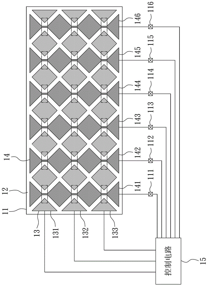
[0008] This leads to an increase in the number and area of ​​the winding wires connecting the touch panel 11 to the control circuit 15, and further increases the demand for the number of pins used in the control circuit 15, resulting in the area of ​​the control circuit 15 and the cost of the total circuit. Increase

Method used


Image

  • Touch panel, touch device and touch point detection method
  • Touch panel, touch device and touch point detection method
  • Touch panel, touch device and touch point detection method

Examples


Embodiment Construction

[0031] The present invention will be described in detail below in conjunction with the drawings and embodiments:

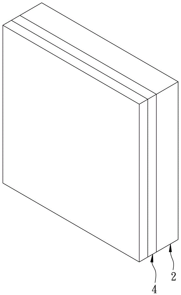
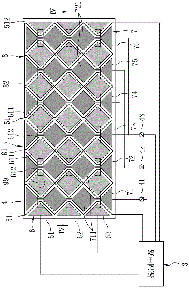
[0032] See figure 2 , image 3 and Figure 4 The preferred embodiment of the touch device of the present invention includes a display panel 2, a control circuit 3, and a touch panel 4.

[0033] The display panel 2 is a familiar content in the industry, so it will not be repeated here.

[0034] The touch panel 4 is disposed opposite to the display panel 2 and is electrically connected to the control circuit 3, and includes a substrate 5, a first electrode unit 6, a second electrode unit 7, and an auxiliary electrode unit 8.

[0035] The substrate 5 includes a side surface 51 and a first touch area 511 and a second touch area 512 respectively formed on the side surface 51.

[0036] In this embodiment, the area of ​​the first touch area 511 and the second touch area 512 are equal, and they are arranged on the left and right. However, the areas of the first touch area 511 and...


PUM


Abstract

The invention provides a touch panel. The touch panel comprises a substrate, a first electrode unit, a second electrode unit and an auxiliary electrode unit, wherein the first electrode unit comprises multiple first electrodes, the second electrode unit comprises multiple first sensing electrodes and multiple second sensing electrodes, the auxiliary electrode unit comprises a first auxiliary electrode and a second auxiliary electrode, the first auxiliary electrode complies with and is not in touch with the first sensing electrodes and is arranged on the substrate, the second auxiliary electrode complies with and is not in touch with the second sensing electrodes and is arranged on the substrate, and the first sensing electrodes and the second sensing electrodes are respectively used for detecting signals of the first auxiliary electrode and the second auxiliary electrode. The touch panel provided by the invention has the effects of reducing output pin positions and reducing the area and the cost of a follow-up control circuit. The invention also provides a touch device and a touch point detection method.

Description

Technical field [0001] The invention relates to a touch technology, in particular to a touch panel, a touch device and a touch point detection method that can reduce the use of feet. Background technique [0002] See figure 1 It shows that an existing touch device includes a touch panel 11 and a control circuit 15. [0003] The touch panel 11 includes a substrate 12, a first electrode unit 13, and a second electrode unit 14. [0004] The first electrode unit 13 includes a plurality of first electrodes 131, 132, 133 disposed on the substrate 12, and the first electrodes 131-133 are arranged at intervals and do not contact each other. [0005] The second electrode unit 14 includes a plurality of second electrodes 141, 142...146 which are respectively disposed on the substrate 12 and interlaced with the first electrodes 131 to 133 and do not contact each other. The second electrodes 141 to 146 respectively A plurality of output pins 111, 112...116 are electrically connected, and the sec...

Claims


Application Information

Patent Timeline
Patent Type & Authority Patents(China)
IPC IPC(8): G06F3/041
Inventor 黄寅修黄俊宏吴嘉源
Owner INNOCOM TECH (SHENZHEN) CO LTD
Learn More