
Liquid crystal display

A liquid crystal display and display technology, applied to static indicators, cathode ray tube indicators, instruments, etc., can solve the problems of high cost, increased size of timing controller 131 and controller 140, etc.

Active Publication Date: 2012-07-04
LG DISPLAY CO LTD
View PDF25 Cites 1 Cited by
  • Summary
  • Abstract
  • Description
  • Claims
  • Application Information

AI Technical Summary

Problems solved by technology

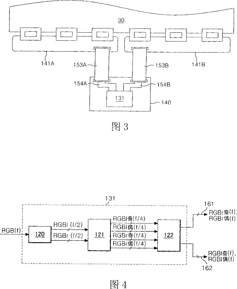
Thus, the number of output pins of the timing controller 131 needs to be twice that of the conventional structure using a single source PCB, which results in increased size and higher cost of the timing controller 131 and the controller 140

Method used


Image

  • Liquid crystal display
  • Liquid crystal display
  • Liquid crystal display

Examples


Embodiment Construction

[0056] The description will serve to describe in detail the preferred embodiments of the invention, examples of which are illustrated in the accompanying drawings. Wherever possible, the same reference numbers will be used throughout the drawings to refer to the same or like parts.

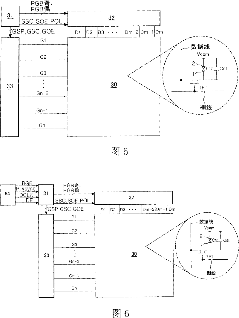
[0057] Figures 5 to 16 shows an LCD device according to a first embodiment of the present invention.

[0058] Such as Figure 5 As shown, the LCD device according to the first embodiment of the present invention includes an LCD panel 30 , a timing controller 31 , a data driving circuit 32 and a gate driving circuit 33 . In the LCD panel 30, a liquid crystal layer is formed between two glass substrates. The LCD panel 30 includes m×n liquid crystal cells Clc arranged in a matrix pattern of m data lines D1 to Dm and n gate lines G1 to Gn.

[0059] Formed on the lower glass substrate of the LCD panel 30 are, among others, data lines D1 to Dm, thin film transistors (TFTs), pixel electrodes 1 of li...


PUM


Abstract

A disclosed display includes a display panel including a first group of data lines and second group of data lines, a plurality of gate lines crossing the first and a second groups of data lines, and a plurality of picture cells arranged in a matrix. The display also includes a first source PCB coupled to first data integrated circuits (ICs) to supply first data voltages to the first group of datalines and a second source PCB coupled to second data ICs to supply second data voltages to the second group of data lines. The display further includes a timing controller having a single output portwith a plurality of output pins which are configured to output video data to both the first and second data ICs, and to output a timing control signal to control both the first and second data ICs. In addition, the display includes a first connection cable coupling the single output port of the timing controller to at least one of the first and second source PCBs to transmit the video data and the timing control signal from the timing controller to the at least one of the first and second source PCBs. The first data ICs and second data ICs are configured to generate the first and second data voltages, respectively, based on the video data and the timing control signal.

Description

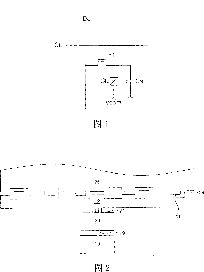
[0001] This application claims Korean Patent Application No. P2007-26070 filed on March 16, 2007; Korean Patent Application No. P2007-0030332, P2007-0030323, P2007-0030333, and P2007- 0030454; the benefit of Korean Patent Application Nos. P2007-0046113 and P2007-0046126 filed May 11, 2007, the entire contents of which are hereby incorporated by reference. technical field [0002] The present invention relates to a liquid crystal display device, and more particularly, to a liquid crystal display device with a simplified control printed circuit board (PCB). Background technique [0003] A liquid crystal display (LCD) device controls light transmittance of a liquid crystal cell according to a video signal to display an image. The active matrix type LCD device actively controls data by switching the data voltage supplied to the liquid crystal cell using a thin film transistor (TFT) formed in each liquid crystal cell Clc, such as figure 1 shown. Thus, it is possible to improve ...

Claims


Application Information

Patent Timeline
Patent Type & Authority Patents(China)
IPC IPC(8): G09G3/36G09G5/00G09G5/06G02F1/133H04N5/765
CPCG09G3/3696G09G2310/0278G09G2310/0286G09G2310/0291G09G2370/14H02M3/04H03K19/1737H03M1/66H05K2201/09972H05K2201/10621
Inventor 宋鸿声闵雄基崔秉辰车东勋张修赫
Owner LG DISPLAY CO LTD
Learn More