Optical fiber distributed type sound wave monitor system

A fiber optic distributed, monitoring system technology, applied in the direction of measuring ultrasonic/sound wave/infrasonic wave, measuring device, using wave/particle radiation, etc., can solve the problems that the phase information cannot be demodulated, and the phase information demodulation of the disturbance signal cannot be realized. , to achieve the effect of improving the signal-to-noise ratio and increasing the optical power

Active Publication Date: 2014-12-03
LASER RES INST OF SHANDONG ACAD OF SCI
View PDF5 Cites 0 Cited by
  • Summary
  • Abstract
  • Description
  • Claims
  • Application Information

AI Technical Summary

Problems solved by technology

[0003] At present, domestic optical fiber distributed monitoring is mainly used in the perimeter security field to determine the disturbance location, such as Φ-OTDR (Phase-Optical Time Domain Reflectometer), but the interference of back Rayleigh scattered light within a unit pulse cannot solve the problem. Calling out the corresponding phase information can only demodulate the intensity change information caused by the phase change, and cannot demodulate the phase information of the disturbance signal at the disturbance position

Method used


Image

  • Optical fiber distributed type sound wave monitor system
  • Optical fiber distributed type sound wave monitor system
  • Optical fiber distributed type sound wave monitor system

Examples


Embodiment 1

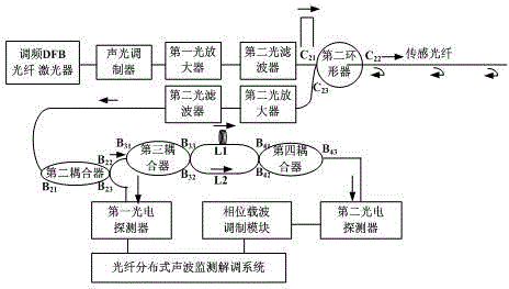
[0017] An optical fiber distributed acoustic wave monitoring system, which uses the frequency-modulated DFB fiber laser output narrow-linewidth, frequency-modulated laser as the laser light source of the optical fiber distributed acoustic wave monitoring system, and is characterized in that the laser output by the frequency-modulated DFB fiber laser enters the The acousto-optic modulator, through the acousto-optic modulator, the continuous laser is modulated into a pulsed laser with a pulse width of τ and a period of T. The pulsed laser passes through the first optical amplifier and the first optical filter in turn and then enters the C of the second circulator. 21 end, the unit pulse laser passes through the C of the second circulator 22 Injection into a sensing fiber with a length of L will excite Rayleigh scattered light within the range of the unit length of the sensing fiber that the unit pulse laser passes through. Because the pulse laser with narrow linewidth has good co...

Embodiment 2

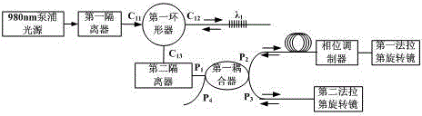
[0045] The similarities between this embodiment and Embodiment 1 will not be repeated, as Figure 8 As shown, the difference from Embodiment 1 is that the back Rayleigh scattering interference is formed in a different way. In this embodiment, the B of the fifth coupler is used. 53 , B 54 The Michelson interferometer with arm length difference S formed at both ends interferes the back Rayleigh scattering signals between different unit lengths. The back Rayleigh scattering signal output by the second optical filter enters the C of the third circulator 31 terminal, from the C of the third circulator 32 end flows into the fifth coupler's B 51 end, through the fifth coupler beam splitting to B 53 and B 54 end, B 53 and B 54 The two ends constitute a Michelson interferometer with arm length difference, B 53 The length of the light at the end is L 1 The optical fiber is reflected by the third Faraday rotating mirror and returns to the fifth coupler B 53 end, B 54 The lengt...

Embodiment 3

[0048] The similarities between this embodiment and Embodiment 1 will not be repeated, as Figure 9 As shown, the difference from Embodiment 1 is that the interference forming method of interfering the back Rayleigh scattering signals between different unit lengths on a sensing fiber using an interferometer is different. In this embodiment, The seventh coupler and the time-delay fiber are the main components to form a time-delay ring Sagnac interferometer to interfere the back Rayleigh scattering signals between different unit lengths.

[0049] Said using the seventh coupler and delay fiber as the main components to form a delay ring Sagnac interferometer to interfere the back Rayleigh scattering signals between different unit lengths refers to the back Rayleigh scattering signal output by the second optical filter The scattered signal enters the B of the sixth coupler 61 end, through the beam splitting of the sixth coupler, all the light enters the C of the fourth circulator...


PUM


Abstract

Provided is an optical fiber distributed type sound wave monitor system. Narrow-linewidth frequency-modulated lasers output by a frequency modulation DFB fiber laser are used as the light source of the optical fiber distributed type sound wave monitor system, the lasers output by the frequency modulation DFB fiber laser enter an acoustic optical modulator and are modulated to be pulse lasers through the acoustic optical modulator, the pulse lasers pass through a first optical amplifier and a first optical filter and then enter a second circulator and sensor fibers, the pulse lasers per unit can emit rayleigh scattering light within the range of the passed sensor fibers per unit length, and signals output by the second circulator pass through a second optical amplifier to enter a second optical filter and output backscattering rayleigh signals. The backscattering rayleigh signals between different unit lengths on one sensor fiber are interfered with the method of an interferometer, the interfered signals pass through electrical signals output by a second photoelectric detector and enter the optical fiber distributed type sound wave monitor demodulation system though a phase carrier demodulation module, and the change analysis of the phases of the sensor signals at corresponding positions is achieved.

Description

technical field [0001] The invention relates to an optical fiber distributed acoustic wave monitoring system. Background technique [0002] Distributed optical fiber sensing technology is a technology that uses the longitudinal characteristics of optical fiber to measure. It regards the measured parameters as a function of the length of the optical fiber, and can continuously measure the external physical parameters distributed along the geometric path of the optical fiber throughout the entire length of the optical fiber. And the research field provides a means to simultaneously obtain the spatial distribution status and time-varying information of the measured physical parameters, and has been widely used in the fields of intelligent aircraft, intelligent bridges, highways, important buildings, gas pipeline monitoring, and optical cable monitoring. [0003] At present, domestic optical fiber distributed monitoring is mainly used in the perimeter security field to determine...

Claims


Application Information

Patent Timeline
Patent Type & Authority Patents(China)
IPC IPC(8): G01H9/00
Inventor 尚盈郭士生刘小会王昌赵文安王晨
Owner LASER RES INST OF SHANDONG ACAD OF SCI
Why Eureka
Try Eureka