Wind forest device

A wind forest and wind blocking technology, applied in the field of wind protection, can solve problems such as damage to crops and trees, land desertification, dust pollution, etc., and achieve the effects of attenuation of kinetic energy, long service life, and quick installation

Active Publication Date: 2013-12-04
SHANXI SHANGFENG TECH
View PDF5 Cites 1 Cited by
  • Summary
  • Abstract
  • Description
  • Claims
  • Application Information

AI Technical Summary

Problems solved by technology

[0002] Strong winds have a huge impact on transportation, agriculture, forestry, construction, and ecology. The damage caused by strong winds can block traffic, damage crops and trees, lead to land desertification, and form dust pollution. At present, the main windproof technology is basically in the end-of-line treatment mode

Method used


Image

  • Wind forest device
  • Wind forest device
  • Wind forest device

Examples


Embodiment 1

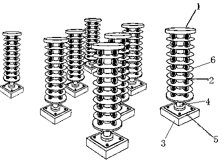
[0023] Embodiment one: figure 1 , figure 2 As shown, this embodiment is formed by a number of wind pillars arranged staggered into multiple rows. The wind pillar is composed of a foundation 3, a wind pillar support frame 1, and a wind blocking rotating body 2. The wind blocking rotating body 2 is installed on the wind pillar supporting frame 1. . The wind column support frame 1 is fixedly installed on the foundation 3 .

[0024] The foundation 3 is a concrete prefabricated slab or a metal slab.

[0025] The wind column support frame 1 is formed by connecting a support column 4 and a base 5 . The choke rotating body 2 is installed on the support column 4 .

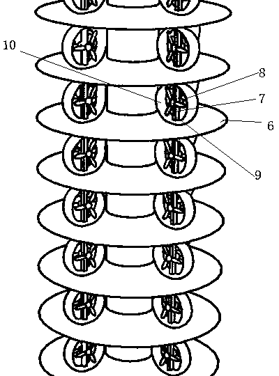
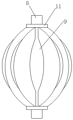
[0026] The wind-blocking rotating body 2 is composed of several rotating units. The rotating unit is composed of an annular plate 6 and a rotating body. The rotating body is installed on the annular plate 6. The annular plate 6 is fixed to the support column 4. The rotating ring 10 is composed of the rotating blade 9 ...

Embodiment 2

[0027] Embodiment 2: This embodiment consists of several wind columns arranged in multiple rows in a staggered manner. The wind column is composed of a foundation, a wind column support frame, and a wind blocking rotating body. The wind blocking rotating body is installed on the wind column supporting frame. The wind column support frame is fixedly installed on the foundation.

[0028] The wind-blocking rotating body is composed of a rotating plate and blades mounted on the rotating plate. The rotating plate is the annular plate 6 in the first embodiment installed together with the supporting column through bearings, and the annular plate 6 rotates around the supporting column.

Embodiment 3

[0029] Embodiment 3: The rotating body in this embodiment is composed of a shaft and a rotating ball mounted on the shaft, and other structures are the same as in Embodiment 1.


PUM


Abstract

The invention discloses a wind forest device, and belongs to a windproof facility. The wind forest device is 2 to 60 meters high and 3 to 300 meters deep, and is characterized by consisting of a plurality of wind columns which are arranged in a row or arranged in a plurality of rows in a staggered way, wherein each wind column consists of a foundation, a wind column support frame and a windproof rotating body; the windproof rotating bodies are arranged on the wind column support frames; the wind column support frames are arranged on the foundations; rotating bodies of the windproof rotating bodies rotate around shafts to change wind directions and consume energy, thereby reducing wind speed. According to the principle of the wind forest device, when strong wind passes through the wind forest device, wind force is used for rotating the windproof rotating bodies of the wind forest device, and wind energy is converted into mechanical energy, so that the kinetic energy and the speed of the wind are effectively reduced, and a windproof effect is achieved.

Description

technical field [0001] The invention belongs to the field of wind protection, and in particular relates to a wind forest device for wind protection. Background technique [0002] Strong winds have a huge impact on transportation, agriculture, forestry, construction, and ecology. The damage caused by strong winds can block traffic, damage crops and trees, lead to land desertification, and form dust pollution. At present, the main windproof technology is basically in the terminal treatment mode. Contents of the invention [0003] The object of the present invention is to provide a wind forest device with simple structure, economical and practical, and good windproof effect, so as to realize the function of windproof. [0004] In order to achieve the above object, the present invention adopts the following solutions: a wind forest device with a height of 2-60 meters and a depth of 3-300 meters; it consists of several wind columns arranged in a row or staggered in multiple row...

Claims


Application Information

Patent Timeline
Patent Type & Authority Applications(China)
IPC IPC(8): F03D11/00F03D3/02F03D3/06F03D1/02F03D1/06
CPCY02E10/721Y02E10/74Y02E10/72
Inventor 张心毅
Owner SHANXI SHANGFENG TECH
Why Eureka
Try Eureka