Processing device for displaying environmental load and method for displaying environmental load

一种环境负荷、显示处理的技术,应用在负荷领域,能够解决难以知道环境负荷等问题

Active Publication Date: 2013-12-04
KONICA MINOLTA INC
View PDF4 Cites 2 Cited by
  • Summary
  • Abstract
  • Description
  • Claims
  • Application Information

AI Technical Summary

Problems solved by technology

[0006] However, it is difficult to know the load on the environment only by the number of single-sided paper used.

Method used


Image

  • Processing device for displaying environmental load and method for displaying environmental load
  • Processing device for displaying environmental load and method for displaying environmental load
  • Processing device for displaying environmental load and method for displaying environmental load

Examples


no. 1 approach

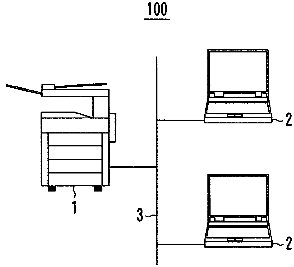
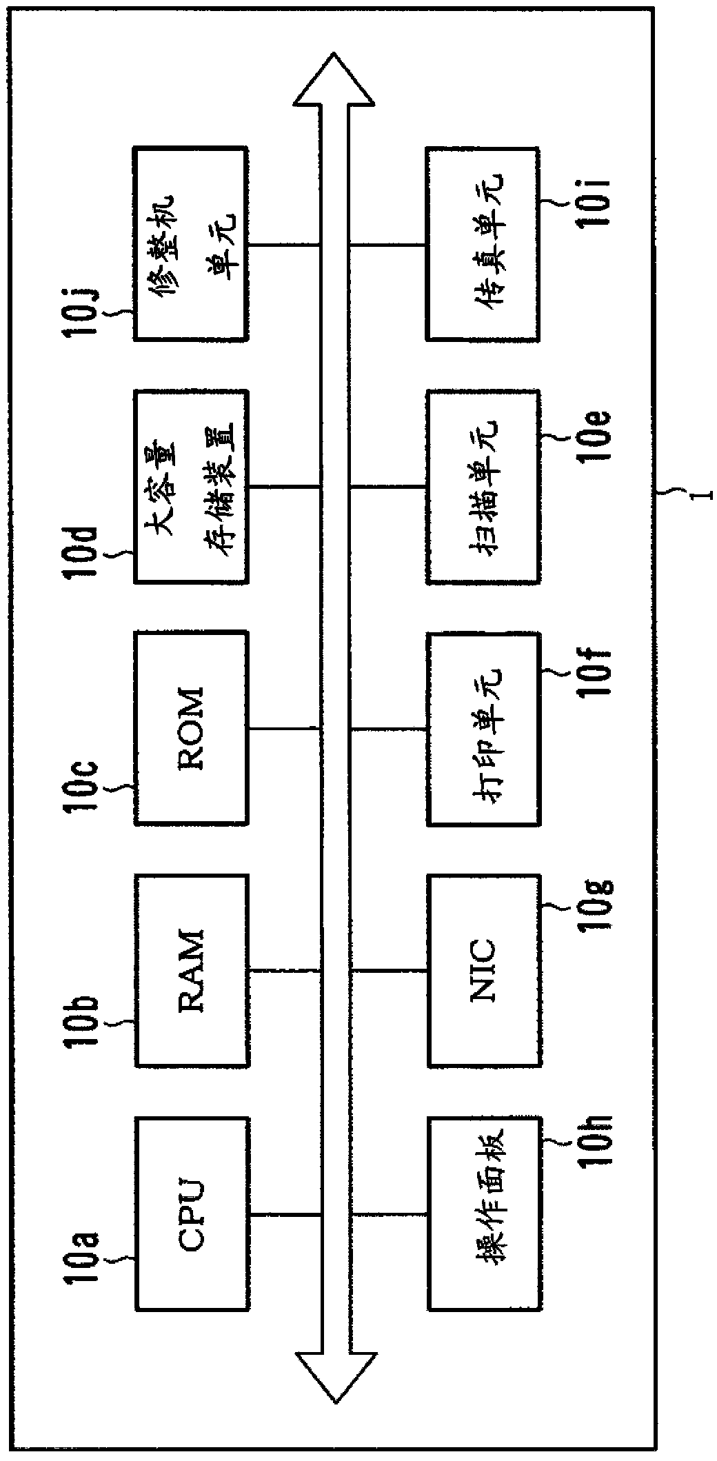
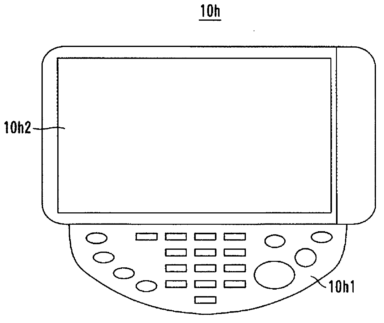
[0058] figure 1 It is a diagram showing an example of the overall configuration of the network printing system 100 . figure 2 It is a diagram showing an example of the hardware configuration of the image forming apparatus 1 . image 3 It is a figure which shows the example of the structure of operation panel 10h. Figure 4 is a diagram showing an example of the configuration of the printing unit 10f. Figure 5 It is a diagram showing an example of the functional configuration of the image forming apparatus 1 .

[0059] Such as figure 1 As shown, the network printing system 100 includes an image forming device 1 , one or more terminal devices 2 , and a communication line 3 and the like.

[0060] Each device of the network printing system 100 can communicate via the communication line 3 . As the communication line 3 , a so-called LAN (Local Area Network) line, a dedicated line, or a public line can be used.

[0061] The image forming apparatus 1 is an apparatus generally ...

no. 2 approach

[0178] Figure 13 It is a diagram showing an example of the functional configuration of the image forming apparatus 1 . Figure 14 It is a diagram showing an example of the finisher setting screen WN3. Figure 15 It is a diagram showing an example of the copy condition setting screen WN2. Figure 16 It is a diagram showing an example of the copy condition setting screen WN2 and the dialog box DG24.

[0179] In the first embodiment, the environmental load of a print job when new paper and single-sided paper are used is notified. In the second embodiment, the environmental load of a print job including processing based on whether the finisher unit 10j is a new product or a reused product (used product) is notified.

[0180] The overall structure of the network printing system 100 in the second embodiment is the same as that in the first embodiment, as figure 1 shown. The hardware structure of the image forming apparatus 1 is also the same as that of the first embodiment, fo...


PUM


Abstract

A computer performs the following processing: calculating a probability that a machine fails in work applied to a printed matter; calculating, as a production environmental load value, a value including a printing environmental load value, a paper environmental load value, a product of the probability and a re-printing environmental load value, and a product of the probability and the paper environmental load value, the printing environmental load value representing a degree of load put on the environment resulting from printing onto paper used for the printed matter, the paper environment load value representing a degree of load put on an environment resulting from production of the paper, the re-printing environmental load value representing a degree of load put on the environment until the printing unit has conducted printing again since the machine failed in the work; and displaying the production environmental load value on the display.

Description

technical field [0001] The present invention relates to a technique for displaying the magnitude of the load imposed on the environment by an image forming apparatus. Background technique [0002] In recent years, in order to protect the natural environment, efforts have been made to save energy and reduce carbon dioxide emissions in various industries. Methods for facilitating these efforts have also been proposed in the field of image forming apparatuses. [0003] For example, a proposal has been proposed to count and display the number of sheets of paper (single-sided paper (liner paper)) that are used for copying in an image forming apparatus with only one side used and the other side unused, thereby Promote the use of single-sided paper and achieve conservation of the natural environment (Patent Document 1). [0004] patent documents [0005] Patent Document 1: (Japanese) Unexamined Patent Publication No. 2001-356648 [0006] However, it is difficult to know the loa...

Claims


Application Information

Patent Timeline
Patent Type & Authority Applications(China)
IPC IPC(8): H04N1/00
CPCH04N1/00472G03G15/00H04N1/00015G03G2215/00109G03G15/502H04N1/00482H04N1/00413G03G15/553H04N1/00092H04N2201/0094H04N1/00068
Inventor 富田茂男小轮瀬一彦
Owner KONICA MINOLTA INC
Why Eureka
Try Eureka