air test

一种空中测试、待测试的技术,应用在测量装置、测量电变量、传输系统等方向,能够解决测试系统复杂且昂贵等问题,达到精确角度功率分布的效果

Active Publication Date: 2015-11-25
KEYSIGHT TECH SINGAPORE (SALES) PTE LTD
View PDF4 Cites 0 Cited by
  • Summary
  • Abstract
  • Description
  • Claims
  • Application Information

AI Technical Summary

Problems solved by technology

But when the number of antenna element-specific channels increases, the test system becomes more complex and expensive

Method used


Image

  • air test
  • air test
  • air test

Examples


Embodiment Construction

[0021] Exemplary embodiments of the present invention will be described more fully hereinafter with reference to the accompanying drawings, in which some, but not all embodiments of the invention are shown. Indeed, the invention may be embodied in many different forms and should not be construed as limited to the embodiments set forth herein; rather, these embodiments are provided so that this disclosure will satisfy applicable legal requirements. Although the specification may refer to "a", "an" or some embodiments in several places, this does not necessarily mean that the same embodiment is referred to every time, nor does it mean that the described features only apply in a single embodiment. Individual features of different embodiments may also be combined to provide other embodiments. Therefore, all words and expressions should be interpreted broadly and are intended to illustrate, not to limit, each embodiment.

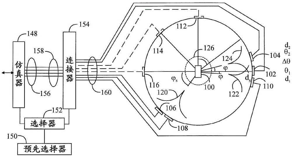
[0022] figure 1 The OTA test chamber is given in planar ...


PUM


Abstract

A pre-selector that forms a plurality of pre-selections by generating a pre-determined number of random positions for each pre-selection, wherein each position is among the pre-determined number of antenna elements surrounding the device under test for use in the over-the-air test an antenna element. The selector selects a preselection from said plurality of preselections for at least one path of the radio channel to be simulated, wherein the absolute error between the theoretical and real spatial correlation corresponding to the preselection is below a predetermined threshold. Connectors connect selected antenna elements at various preselected locations with the radio channel emulator to physically implement the simulated radio channel for the device under test and the radio channel emulator.

Description

technical field [0001] The present invention relates to over-the-air testing of devices in an echogenic chamber. Background technique [0002] When a radio frequency signal is transmitted from a transmitter to a receiver, the signal travels in a radio channel along one or more paths with different angles of arrival, signal delays, polarizations, and powers, resulting in the received Fades of different duration and strength in the signal. Additionally, noise and interference due to other transmitters can interfere with the radio connection. [0003] Transmitters and receivers can be tested using radio channel emulators that simulate real conditions. In digital radio channel emulators, the radio channel is usually modeled with an FIR filter (Finite Impulse Response). Traditional radio channel emulation testing is performed with a lead-through connection where the transmitter and receiver are coupled together by a cable. [0004] Communication between a subscriber terminal ...

Claims


Application Information

Patent Timeline
Patent Type & Authority Patents(China)
IPC IPC(8): H04B17/391G01R29/08H01Q3/24H01Q3/26
CPCG01R29/0821H04B17/0085H04B17/391H04B17/0087H04B17/3911G01R29/08G01R29/10
Inventor J-P·努蒂宁P·屈厄斯蒂
Owner KEYSIGHT TECH SINGAPORE (SALES) PTE LTD
Why Eureka
Try Eureka