Over-the-air test

An aerial test and to-be-tested technology, applied in measurement devices, measurement of electrical variables, transmission systems, etc., can solve the problems of complex and expensive test systems, and achieve the effect of accurate angular power distribution

Active Publication Date: 2013-12-04
KEYSIGHT TECH SINGAPORE (SALES) PTE LTD
View PDF4 Cites 4 Cited by
  • Summary
  • Abstract
  • Description
  • Claims
  • Application Information

AI Technical Summary

Problems solved by technology

But when the number of antenna element-specific channels increases, the test system becomes more complex and expensive

Method used


Image

  • Over-the-air test
  • Over-the-air test
  • Over-the-air test

Examples


Embodiment Construction

[0021] Exemplary embodiments of the present invention will be described more fully hereinafter with reference to the accompanying drawings, in which some, but not all embodiments of the invention are shown. Indeed, the invention may be embodied in many different forms and should not be construed as limited to the embodiments set forth herein; rather, these embodiments are provided so that this disclosure will satisfy applicable legal requirements. Although the specification may refer to "a", "an" or some embodiments in several places, this does not necessarily mean that the same embodiment is referred to every time, nor does it mean that the described features only apply in a single embodiment. Individual features of different embodiments may also be combined to provide other embodiments. Therefore, all words and expressions should be interpreted broadly and are intended to illustrate, not to limit, each embodiment.

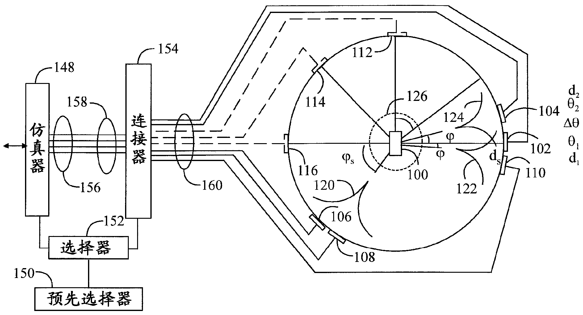
[0022] figure 1 The OTA test chamber is given in planar ...


PUM


Abstract

A preselector forms a plurality of preselections, by generating, for each preselection, a predetermined number of random locations, each location being for an antenna element of the predetermined number of antenna elements around a device under test in an over-the-air test. A selector selects, for at least one path of a radio channel to be simulated, a preselection from among the plurality of preselections for which an absolute error between a theoretical and real spatial correlation is below a predetermined threshold. A connector connects the antenna elements at the locations of the selected preselection and the radio channel emulator together for physically realizing the simulated radio channel for the device under test and the radio channel emulator.

Description

technical field [0001] The present invention relates to over-the-air testing of devices in an echogenic chamber. Background technique [0002] When a radio frequency signal is transmitted from a transmitter to a receiver, the signal travels in a radio channel along one or more paths with different angles of arrival, signal delays, polarizations, and powers, resulting in the received Fades of different duration and strength in the signal. Additionally, noise and interference due to other transmitters can interfere with the radio connection. [0003] Transmitters and receivers can be tested using radio channel emulators that simulate real conditions. In digital radio channel simulators, the radio channel is usually modeled with an FIR filter (Finite Impulse Response). Traditional radio channel emulation testing is performed with a lead-through connection where the transmitter and receiver are coupled together by a cable. [0004] Communication between a subscriber terminal...

Claims


Application Information

Patent Timeline
Patent Type & Authority Applications(China)
IPC IPC(8): H04B17/00G01R29/08H01Q3/24H01Q3/26
CPCH04B17/009G01R29/0821H04B17/0085H04B17/391H04B17/0087H04B17/3911G01R29/08G01R29/10
Inventor J-P·努蒂宁P·屈厄斯蒂
Owner KEYSIGHT TECH SINGAPORE (SALES) PTE LTD
Why Eureka
Try Eureka