A method and device for multi-cell joint coverage optimization of a cellular mobile communication network

A cellular mobile communication and coverage optimization technology, applied in wireless communication, network planning, electrical components, etc., can solve problems such as growth and large amount of computation

Inactive Publication Date: 2016-08-10
ZHEJIANG UNIV +1
View PDF5 Cites 0 Cited by
  • Summary
  • Abstract
  • Description
  • Claims
  • Application Information

AI Technical Summary

Problems solved by technology

However, the former method involves the boundary division of multiple cells and the iterative solution of the antenna excitation weight vector, while the latter method traverses the possible transmit power, excitation current amplitude and phase of multi-cell antennas to find the optimal solution, which requires a large amount of computation and is random Exponential growth with the number of cells

Method used


Image

  • A method and device for multi-cell joint coverage optimization of a cellular mobile communication network
  • A method and device for multi-cell joint coverage optimization of a cellular mobile communication network
  • A method and device for multi-cell joint coverage optimization of a cellular mobile communication network

Examples


Embodiment 1

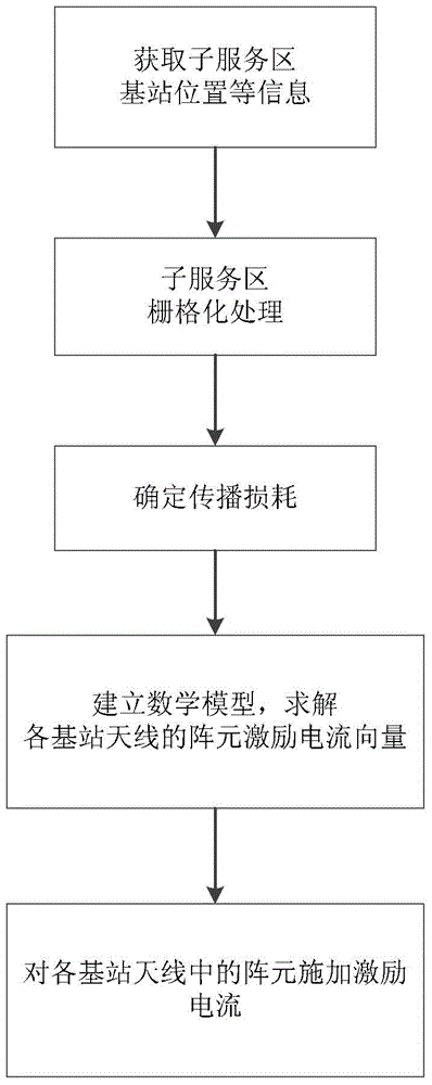
[0056] Such as figure 1 As shown, a method for optimizing joint coverage of multiple cells in a cellular mobile communication network in Embodiment 1 includes the following steps:

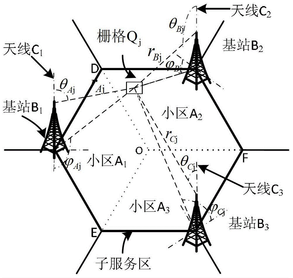
[0057] (1) For any sub-service area in the cellular mobile communication network, collect the location information of each base station in the sub-service area; figure 2 As shown, the sub-service area consists of three adjacent and opposite 120° cells A 1 ~A 3 Composition, the base stations of the three cells are respectively denoted as B 1 ~B 3 , the antennas of the three base stations are denoted as C 1 ~C 3 ;

[0058] The adjacency mentioned means that the three cells are close to each other geographically. The relative means that the main beams of the base station antennas of the three cells are directed to the same area.

[0059] (2) rasterize the sub-service area, and record the total number of grids in the sub-service area, the apex of each grid and the positional coordinates of the...

Embodiment 2

[0113] The coverage optimization method of this embodiment can also be used to correct the bad coverage of a single cell separately, including the following steps:

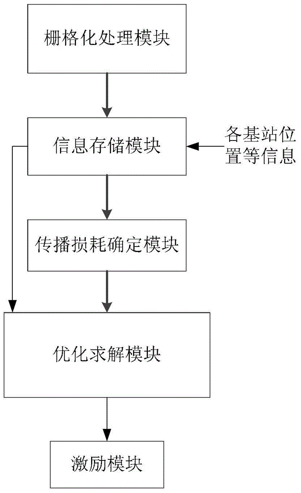
[0114] (1) Use the cell and the other two adjacent cells to form a sub-service area, and collect information such as the base station location and antenna parameters of the sub-service area;

[0115] (2) Carry out grid division to this sub-service area, obtain the total number of grids, the vertex of each grid and the positional coordinates of center point;

[0116] (3) Obtain the propagation loss from each base station antenna to the center point of each grid; the propagation loss can be measured in the actual network, or calculated by the propagation loss model;

[0117] (4) According to the propagation loss, establish a mathematical model with the weak coverage area ratio as the minimization target and the over coverage area ratio as the constraint condition;

[0118] (5) Solve the mathematical model to obtain...


PUM


Abstract

The invention discloses a multi-cell joint coverage optimization method of a cellular mobile communication network, which includes the following steps: (1) collecting the position of each base station in a sub-service area and information on each antenna parameter; (2) recording each sub-service area after rasterization The position coordinates of the vertices and center points of each grid; (3) determine the wireless signal propagation loss from each grid center point to each base station antenna; (4) establish the weak coverage area ratio as the minimum target and the over coverage area (5) After solving the mathematical model, apply the excitation current to the array element in the base station antenna according to the obtained excitation current vector of the base station array element. The invention also discloses a coverage optimization device for realizing the above method, including a control unit; the control unit includes a grid processing module, an information storage module, a propagation loss determination module, an optimization solution module and an excitation module. The present invention minimizes areas of weak coverage while eliminating areas of overcoverage.

Description

technical field [0001] The invention relates to the field of cellular mobile communication, in particular to a multi-cell joint coverage optimization method and device for a cellular mobile communication network. Background technique [0002] The goal of cellular mobile communication network coverage optimization is to optimize the coverage of public control signals (pilot, synchronization, etc.) of each cell to achieve seamless coverage of public control signals in the network and low mutual interference between cells. Due to factors such as base station site selection restrictions, obstacles blocking, and topography (radio signal propagation conditions) changes, the actual coverage area of ​​the cell often does not match the planned coverage area, which is manifested in poor coverage, including weak coverage and over-coverage. In the weak coverage area, the received common control signal power of each base station is lower than the specified decision threshold Therefore,...

Claims


Application Information

Patent Timeline
Patent Type & Authority Patents(China)
IPC IPC(8): H04W16/18
Inventor 黄爱苹范东东武洲云单杭冠王成庄宏成
Owner ZHEJIANG UNIV
Why Eureka
Try Eureka