Splicer devices and winders for splicing yarns

A splicer and winding machine technology, applied in the field of winding machines, can solve the problems of complex pneumatic splicing process and extremely complex requirements of yarn, and achieve the effect of cost-effectiveness and efficiency advantages

Active Publication Date: 2017-04-12
SAVIO MACCHINE TESSILI
View PDF11 Cites 0 Cited by
  • Summary
  • Abstract
  • Description
  • Claims
  • Application Information

AI Technical Summary

Problems solved by technology

[0017] In these patents, as well as in currently available splicers, it can be seen that the process of pneumatic splicing of yarns is very complex and requires extremely complex splicers

Method used


Image

  • Splicer devices and winders for splicing yarns
  • Splicer devices and winders for splicing yarns
  • Splicer devices and winders for splicing yarns

Examples


Embodiment Construction

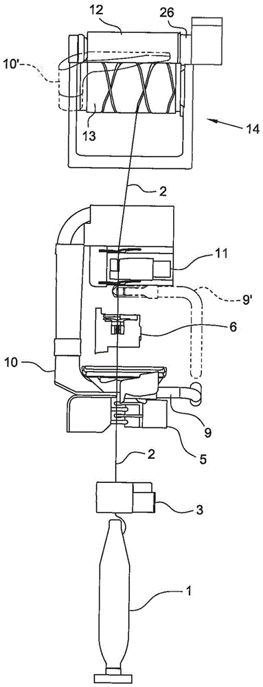
[0041] figure 1 A diagram of the yarn collection unit in the winder is shown in the form of a front view, in which the most important elements involved in the process of forming the package are shown and technical issues are explained. Figures 2A-2G The steps of the yarn splicing process with the splicer device according to the invention are shown with reference to an exploded view of the main elements of the splicer device according to the invention.

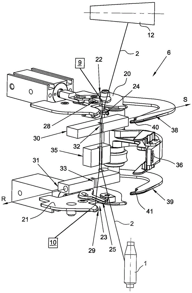
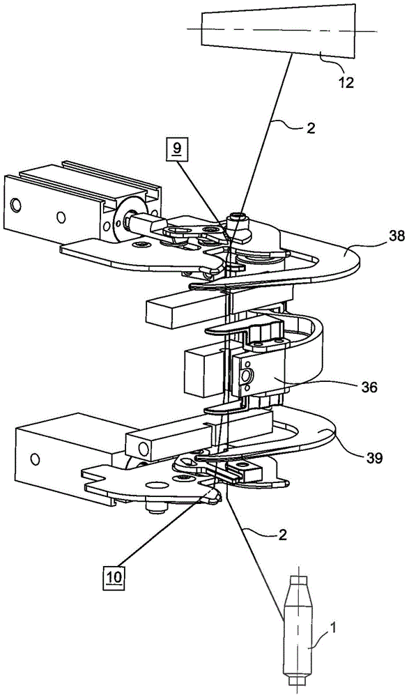
[0042] Figure 2A The splicer arrangement is shown in initial step 1, where the yarn ends are brought to the splicer from the pack side inlet and the feed rocker side inlet, with the following components shown in exploded view:

[0043] 20, 21: upper and lower guide plates of the yarn leading to the splicer, wherein, according to one embodiment, these upper guide plates 20 and lower guide plates 21 are made to be fixed plates;

[0044] 22, 23: upper yarn guide cavity and lower yarn guide cavity,

[0045] 24 , 25 : upper and...


PUM


Abstract

Splicer device (6) for splicing yarns in a winding machine wherein the yarn (2) is fed from the bottom and wound from the top on a package (12) and comprising upper (24) and lower (25) clamping members and upper (28) and lower (29) shear members, wherein the upper clamp and shears are sequentially actuated by an upper actuator (50) which firstly closes the upper clamp and then actuates the upper shears, and wherein also the lower clamp and shears are sequentially actuated by a lower actuator (51) which firstly closes the lower clamp and then actuates the lower shears, said actuators being fed in parallel by a feeding device (76) which is common to the two actuators.

Description

technical field [0001] The invention relates to a splicer device for splicing yarns during their winding on a tube to achieve the formation of a collected package of yarns produced or processed by a textile machine. The invention also relates to a winding machine comprising such a splicer device. Background technique [0002] In industrial practice, it is widely dominant to rotatably drive the tube (idly carried by the spindle of the package holder arm) and to withdraw the yarn from the follower to be wound on Yarn collection technology on it. The package is thus formed by pulling and winding the yarn on its surface, the package being rotatably drawn by an underlying motor-driven roller on which the package itself is supported. In this way, the yarn can be wound at a constant linear speed, independent of the dimensions acquired by the package as the winding progresses, and only as a function of the rotational speed of said drive roller. [0003] In order to further clarif...

Claims


Application Information

Patent Timeline
Patent Type & Authority Patents(China)
IPC IPC(8): B65H69/06
CPCB65H69/063B65H2701/31
Inventor 罗伯托·巴迪亚利毛罗·戴尔 皮普默雷诺·弗洛里杜兹丹特·赞凯
Owner SAVIO MACCHINE TESSILI
Why Eureka
Try Eureka