Electronically controlled swing type soldering iron cooling rack

An electric soldering iron, swing-type technology, applied in the direction of soldering irons, auxiliary devices, metal processing equipment, etc., can solve the problems of easy oxidation of soldering iron tips, energy waste, short time, etc.

Active Publication Date: 2015-10-21
QIDONG QINGQING VEGETABLE & FRUIT RURAL LAND STOCK PROFESSIONAL COOP
View PDF7 Cites 0 Cited by
  • Summary
  • Abstract
  • Description
  • Claims
  • Application Information

AI Technical Summary

Problems solved by technology

[0002] At present, although the adjustable constant temperature electric soldering irons on the market can control the working temperature range of the electric soldering iron, it is unavoidable to place the electric soldering iron temporarily due to the board circuit or personnel relationship during the use of the electric soldering iron. Short-lived, that is, the dormant state. At this time, although the electric soldering iron is in the set constant temperature state, because the heat is relatively concentrated, the soldering iron tip is easy to oxidize, and at the same time, it also causes a waste of energy

Method used


Image

  • Electronically controlled swing type soldering iron cooling rack
  • Electronically controlled swing type soldering iron cooling rack
  • Electronically controlled swing type soldering iron cooling rack

Examples


Embodiment Construction

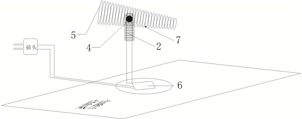
[0013] The present invention is an electronically controlled swing type electric soldering iron cooling rack, which is composed of: a resistor 1, a motor 2, a capacitor 3, a gear 4, a sleeve 5, a control module 6, and a sensor 7.

[0014] exist figure 1 Among them, the base is connected with the motor by means of a bracket, the motor is set on the side of the gear, the gear is installed on the side of the sleeve, a sensor is installed under the sleeve, and the control module is installed on the base.

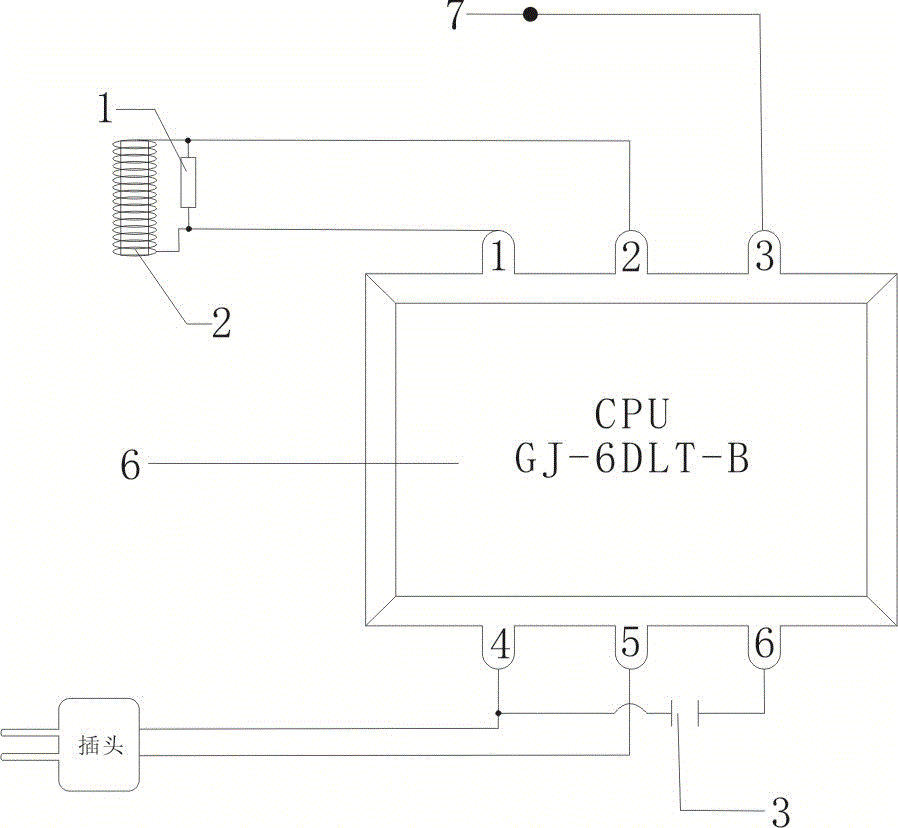
[0015] exist figure 2 Among them, the first pin and the second pin of the control module 6 are respectively connected in parallel to the two ends of the motor 2 and the two ends of the resistor 1, the third pin is connected to the sensor 7, and the fourth pin and the fifth pin lead to a power plug, and at the same time A capacitor 3 is connected in series between the fourth pin and the sixth pin.

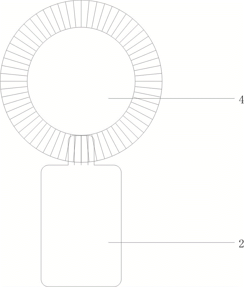
[0016] exist image 3 Among them, the running wheel of the motor 2 is combine...


PUM


Abstract

An electronic control swing type electric soldering iron heat dissipation frame is composed of a resistor, a motor, a capacitor, a gear, a sleeve, a control module and a sensor. The electronic control swing type electric soldering iron heat dissipation frame is characterized in that a first pin of the control module is connected with the two ends of the motor and the two ends of the resistor in parallel, a second pin of the control module is connected with the two ends of the motor and the two ends of the resistor in parallel, a third pin of the control module is connected with the sensor, a power supply plug is drawn from a fourth pin of the control module and a fifth pin of the control module, and meanwhile the capacitor is connected between the fourth pin of the control module and a sixth pin of the control module in series. When the sensor detects that the electric soldering iron is in the sleeve and the stay time exceeds 5 seconds, the control module enables the motor to be powered on so that the gear can stop after rotating by a certain angle, after the stay time is reached, the control module commands the motor to rotate backward so that the gear can rotate to the original starting position, after the stay time of the gear in the starting position is reached, the control module commands the motor to rotate forward again, the gear stops again after rotating to the angle of the previous corner, circulation is conducted in that way, and the function of lowering the temperature of a soldering iron head can be achieved with the help of the swinging of the sleeve.

Description

technical field [0001] The invention relates to the temperature control technology of the electric soldering iron when it is in use, in particular to an electronically controlled swing type electric soldering iron cooling rack. Background technique [0002] At present, although the adjustable constant temperature electric soldering irons on the market can control the working temperature range of the electric soldering iron, it is unavoidable to place the electric soldering iron temporarily due to the board circuit or personnel relationship during the use of the electric soldering iron. Short-lived, that is, the dormant state. At this time, although the electric soldering iron is in the set constant temperature state, due to the relatively concentrated heat, the soldering iron tip is easy to oxidize, and at the same time, it also causes a waste of energy. Contents of the invention [0003] The object of the present invention is to provide an electronically controlled swing ...

Claims


Application Information

Patent Timeline
Patent Type & Authority Patents(China)
IPC IPC(8): B23K3/08B23K3/03
CPCB23K3/08B23K3/085
Inventor 庄景阳
Owner QIDONG QINGQING VEGETABLE & FRUIT RURAL LAND STOCK PROFESSIONAL COOP
Why Eureka
Try Eureka