U upright bracket of switch cabinet

A technology of column support and switchgear, applied in substation/switch layout details, electrical components, etc., can solve the problems of poor applicability, inability to use, and inconvenient installation of other parts, and achieve the effect of low cost, reasonable structure, and convenient use

Active Publication Date: 2014-01-22
广东裕邦电气有限公司
View PDF4 Cites 2 Cited by
  • Summary
  • Abstract
  • Description
  • Claims
  • Application Information

AI Technical Summary

Problems solved by technology

[0004] The bend needs to be stuck and hung on the edge of the column, which limits the placement of the bracket. When the bracket needs to be installed in the middle of the column, it cannot be used; and the bend protrudes from the edge of the column, which brings difficulties for the installation of other components. inconvenient
The edges of the three surfaces used to install the beam are connected to form a U shape, which limits the size of the beam, resulting in the need to replace the bracket with a suitable size when installing different beams, which has poor applicability

Method used


Image

  • U upright bracket of switch cabinet
  • U upright bracket of switch cabinet
  • U upright bracket of switch cabinet

Examples


Embodiment 1

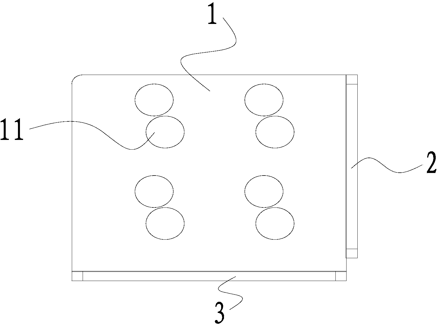
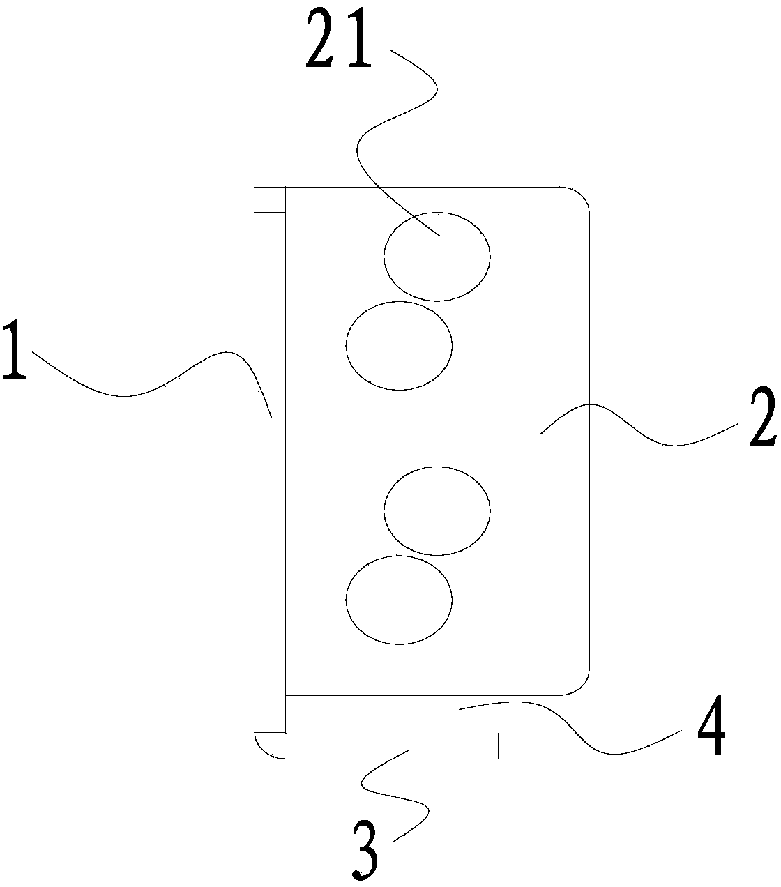
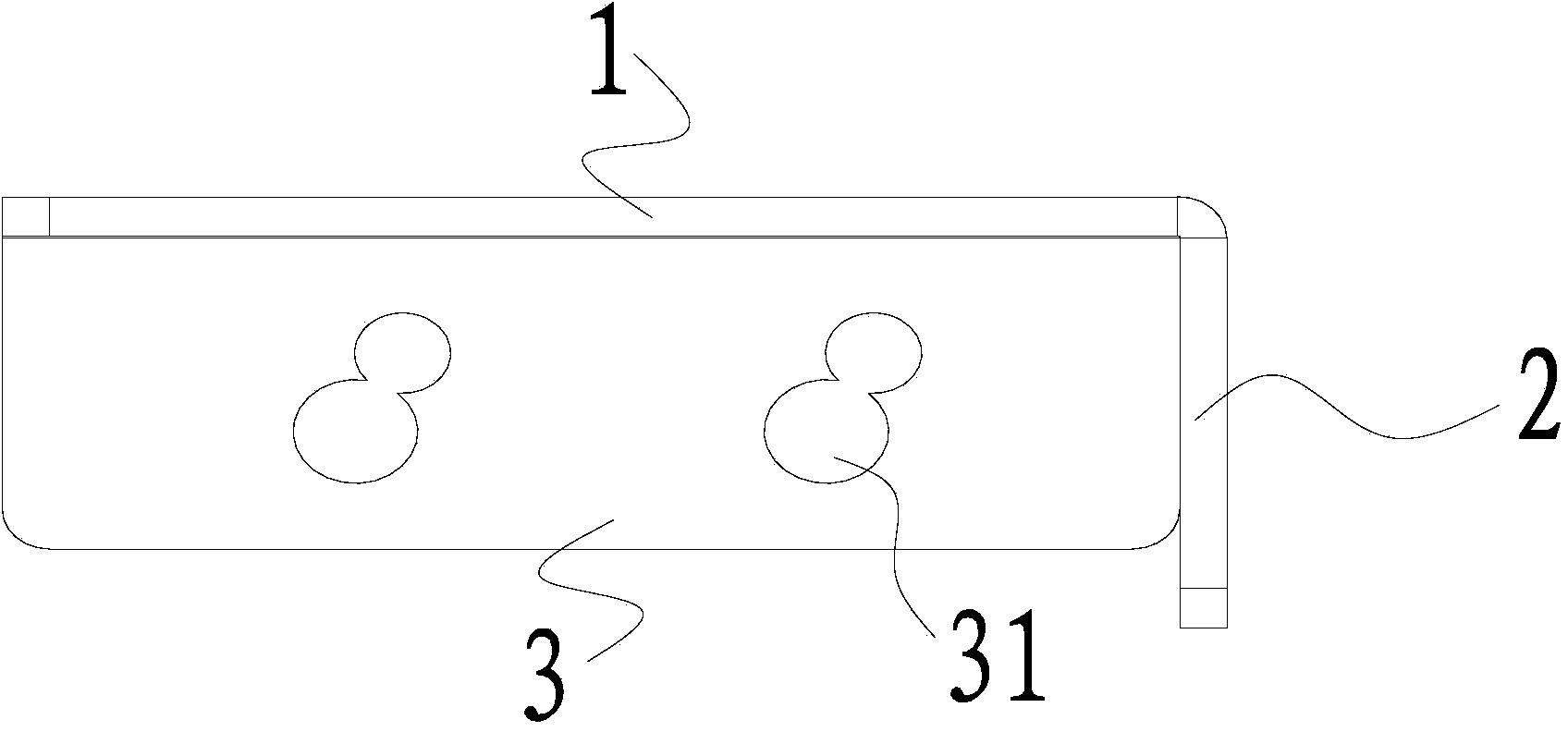
[0026] Such as Figure 1 to Figure 4 As shown, this preferred embodiment provides a switch cabinet U column bracket, the bracket includes a sheet-shaped connecting plate 1, a sheet-shaped baffle plate 2 connected to the connecting plate 1 and a sheet-shaped support connected to the connecting plate 1 The plate 3 is provided with mounting holes on the connecting plate 1, the baffle plate 2 and the support plate 3 respectively. The baffle plate 2 and the support plate 3 are respectively perpendicular to the connecting plate 1, and the baffle plate 2 and the support plate 3 are basically at right angles.

[0027] In order to make the bracket more versatile, a gap 4 is formed between the baffle plate 2 and the support plate 3 . When the edge of the U column is not smooth enough or the verticality of the two surfaces corresponding to the baffle plate 2 and the support plate 3 is not enough, the U column can still be well fixed by the bracket through the adjustment of the gap 4 . ...

Embodiment 2

[0034] This preferred embodiment provides a switch cabinet U column support, the structure of which is basically the same as that of the preferred embodiment 1. The bracket includes a connecting plate, a baffle plate and a supporting plate, and mounting holes are respectively arranged on the connecting plate, the baffle plate and the supporting plate. The baffle plate and the support plate are respectively perpendicular to the connection plate, and the baffle plate and the support plate are basically at right angles.

[0035] The difference is that the specific structural relationship between the baffle plate and the support plate is not limited, they can be connected together or a gap can be left. Taking the connecting plate as the reference plane, the height of the baffle plate can be different from that of the supporting plate, or can be the same, as long as it does not affect the installation of the U column. The number, shape and arrangement of the mounting holes on the ...


PUM


Abstract

The invention discloses a U upright bracket of a switch cabinet and belongs to the field of switch cabinet device components. The U upright bracket is designed to solve the problem of poor generality of the existing bracket. The U upright bracket of the switch cabinet comprises a sheeted connecting plate, a sheeted baffle connected with the connecting plate, and a sheeted support plate connected with the connecting plate, wherein mounting holes are formed in the connecting plate, the baffle and the support plate respectively; the baffle and the support plate are perpendicular to the connecting plate, respectively; and the baffle is basically perpendicular to the support plate. A gap is formed between the baffle and the support plate. The U upright bracket of the switch cabinet is reasonable in structure, convenient to use and low in cost, and is applicable to mounting and fixing of various U uprights.

Description

technical field [0001] The invention relates to a U column support of a switch cabinet. Background technique [0002] High and low voltage switchgear is a kind of industrial power distribution facility, which is widely used in power plants, industrial and commercial buildings, high-rise residential buildings and other environments. The frame of the switch cabinet is formed by connecting beams and columns. If only bolts are used to connect, the tension between the beam and the column is not enough, so that the switchgear cannot be used safely and stably. Usually a bracket is used to connect the beam and column. [0003] The existing bracket adopts four surfaces to form a semi-enclosed structure, and the bracket is fixed on the column by using the bending and bolt holes on one surface, and the beam is installed by using the bolt holes on the other three surfaces. [0004] The bend needs to be stuck and hung on the edge of the column, which limits the placement of the bracke...

Claims


Application Information

Patent Timeline
Patent Type & Authority Applications(China)
IPC IPC(8): H02B1/01
Inventor 吴存林吴浩
Owner 广东裕邦电气有限公司
Why Eureka
Try Eureka