Supercharge Your Innovation With Domain-Expert AI Agents!

Dry clutch friction plate assembly

A dry clutch and friction plate technology, applied in the field of clutches, can solve problems such as inconsistent operating performance

Inactive Publication Date: 2014-01-29
GM GLOBAL TECH OPERATIONS LLC
View PDF8 Cites 2 Cited by
  • Summary
  • Abstract
  • Description
  • Claims
  • Application Information

AI Technical Summary

Problems solved by technology

In addition, the coefficient of friction of friction materials is highly dependent on temperature as temperature increases, causing inconsistencies in operating performance

Method used


Image

  • Dry clutch friction plate assembly
  • Dry clutch friction plate assembly
  • Dry clutch friction plate assembly

Examples


Embodiment Construction

[0061] The following description is merely exemplary in nature and in no way intended to limit the invention, application, or use.

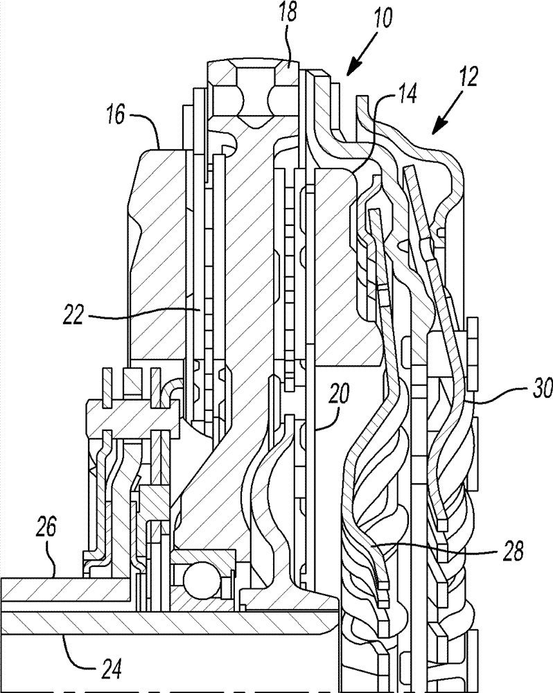
[0062] Referring to the drawings, wherein like reference numerals refer to like parts, in figure 1 In , a radial view of the dual clutch torque transmitting assembly 10 is illustrated and will now be described in accordance with an example of the present invention. The dual clutch torque transmitting assembly 10 includes an input assembly 12; first and second clutch apply members or plates 14, 16; a clutch support member 18, first and second clutch friction plate assemblies 20, 22 and first and second transmission input Members or shafts 24,26. The input assembly 12 is rotationally driven by, for example, a flywheel or other type of engine output member (not shown). The first and second clutch apply members 14 , 16 are in turn rotationally driven by the input assembly 12 and are axially movable via actuation of the first and second spring plate...


PUM


Abstract

A friction plate assembly for use in a dry clutch, the friction plate assembly includes a hub and support member, a first friction disc, a second friction disc, and a plurality of silicone-based adhesive beads disposed between each of the first friction disc and the second friction disc. The adhesive beads are disposed in a pattern designed to create a cooling air pathway from the interior of the friction plate assembly to the exterior.

Description

technical field [0001] The present invention relates generally to clutches for multi-speed transmissions, and more particularly to dry clutch friction plates for clutches. Background technique [0002] The statements in this section merely provide background information related to the present disclosure and may or may not constitute prior art. [0003] A typical dry dual clutch assembly includes at least one friction plate for each clutch. The friction disc includes friction material adhered to the facing surface of the disc's steel backing plate. Through normal operation, heat energy generated by clutch engagement increases the temperature of the friction material of the friction discs. In addition, the coefficient of friction of the friction material is highly dependent on temperature as the temperature increases, causing inconsistencies in operational performance. Operating clutch components at consistently lower temperatures will improve the friction performance of th...

Claims


Application Information

Patent Timeline
Patent Type & Authority Applications(China)
IPC IPC(8): F16D13/60F16D13/64F16D13/72
CPCF16D13/64F16D13/72F16D21/06F16D2021/0615F16D2300/0212
Inventor J.M.克雷默
Owner GM GLOBAL TECH OPERATIONS LLC
Features
  • R&D
  • Intellectual Property
  • Life Sciences
  • Materials
  • Tech Scout
  • Unparalleled Data Quality
  • Higher Quality Content
  • 60% Fewer Hallucinations
Learn More