Contact lens

A contact lens and lens technology, applied in the field of glasses, can solve problems such as inability to effectively prevent eye fatigue, lack of micro-electrical physiotherapy functions, etc.

Active Publication Date: 2014-01-29
NEWNAGY TANGSHAN
View PDF2 Cites 5 Cited by
  • Summary
  • Abstract
  • Description
  • Claims
  • Application Information

AI Technical Summary

Problems solved by technology

[0004] The invention provides a contact lens, which is used to solve the problem that the contact lenses in the prior art cannot effectively prevent eye fatigue because they do not have the function of micro-electric therapy

Method used


Image

  • Contact lens
  • Contact lens
  • Contact lens

Examples


Embodiment 1

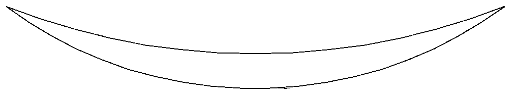
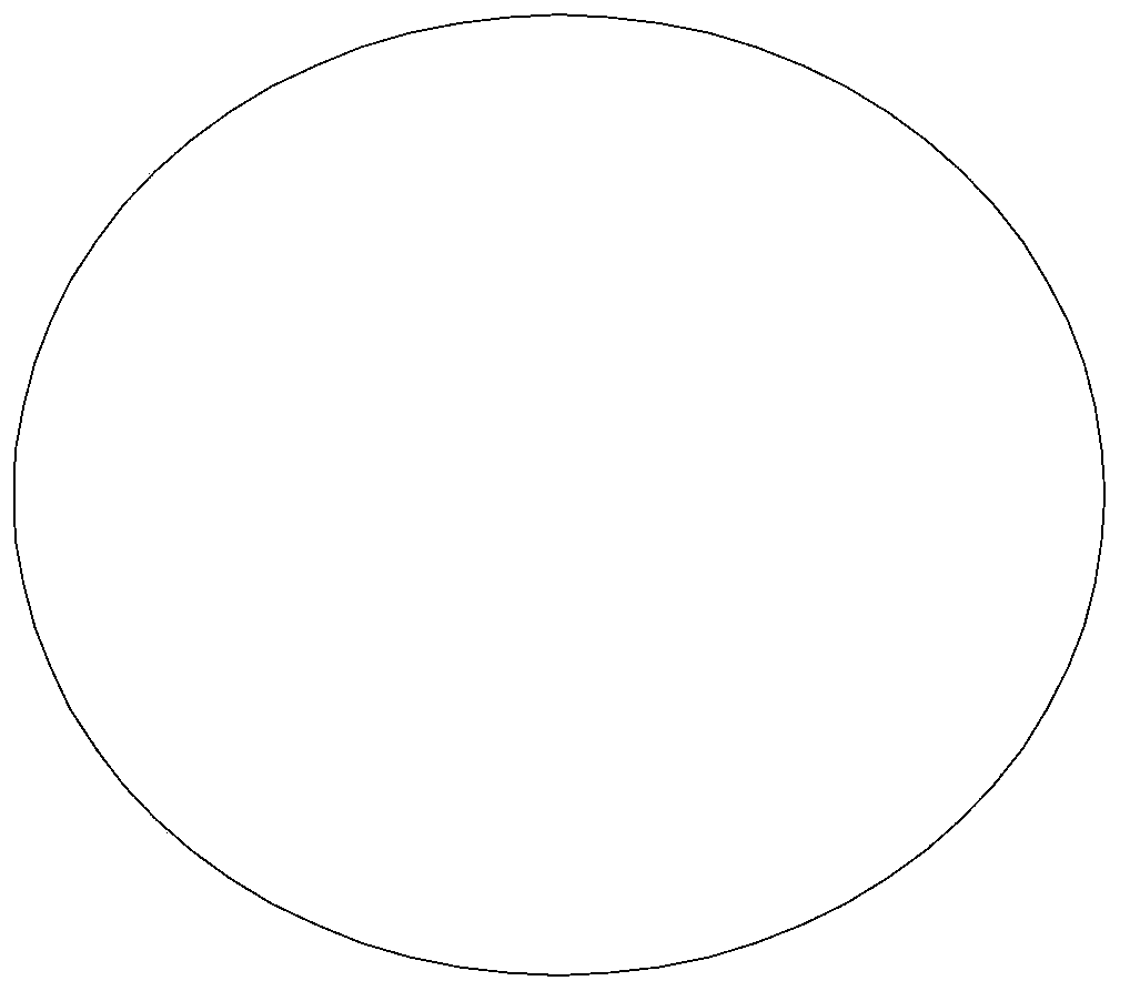
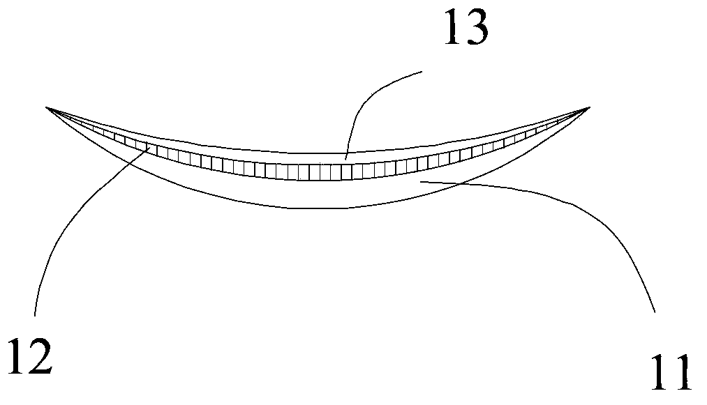
[0026] Figure 2a and Figure 2b A side view and a top view of the contact lens provided by Embodiment 1 of the present invention are respectively shown. As shown in the figure, the contact lens in this embodiment includes: a lens body 11, which is a circular lens with a convex outer surface and a concave inner surface; a piezoelectric nanowire array 12, vertically grown On the inner surface of the lens body 11 and cover the entire inner surface of the lens body 11 ; the insulating layer 13 covers the piezoelectric nanowire array 12 .

[0027] In this embodiment, the piezoelectric nanowire array 12 is grown on the entire inner surface of the lens body 11, so that, on the one hand, the intensity of the microcurrent generated by the piezoelectric nanowire array is improved, and the massage effect is enhanced; on the other hand, It also simplifies the difficulty of making contact lenses.

[0028] Introduce the manufacture method of the contact lens in the present embodiment be...

Embodiment 2

[0038] Figure 4a and Figure 4bA side view and a top view of the contact lens provided by Embodiment 2 of the present invention are respectively shown. As shown in the figure, the contact lens in this embodiment includes: a lens body 11, the lens body 11 is circular, and has a convex outer surface and a concave inner surface, and, on the outer edge of the inner surface An annular groove 10 is provided; the piezoelectric nanowire array 12 is vertically grown in the annular groove 10, and the upper layer of the piezoelectric nanowire array 12 is in the same curved surface as the inner surface of the lens main body 11; the insulating layer 13 , covering the piezoelectric nanowire array 12 .

[0039] In this embodiment, an annular groove is formed on the outer edge of the inner surface of the lens body, so that the piezoelectric nanowire array grows vertically in the annular groove. Because the piezoelectric nanowire array is only distributed on the outer edge of the contact l...


PUM


Abstract

The invention discloses a contact lens and aims at solving the problem in the prior art that the contact lenses are incapable of effectively preventing eye fatigue due to the lack of the micro-electro physical therapy function. The contact lens comprises a lens main body, a piezoelectric material layer and an insulation layer, wherein the lens main body is provided with a first surface and a second surface; the piezoelectric material layer vertically grows on the first surface of the lens main body; the insulation layer covers the piezoelectric material layer. According to the embodiment of the invention, the lens main body of the contact lenses is provided with the piezoelectric material layer; when the user wearing contact lenses blinks, the piezoelectric material layer stresses or deforms due to rotation or extrusion, so that a microcurrent is generated between eyelid and eyeball, thus the micro-electro physical therapy effect is realized.

Description

technical field [0001] The invention relates to the field of glasses, in particular to a contact lens. Background technique [0002] With the rapid development and progress of society, people's study and work pressure is increasing, and the phenomenon of excessive eye use is very common, resulting in an increasing incidence of myopia. Therefore, the wearing rate of contact lenses is also increasing year by year. The side view and top view of existing contact lens are respectively as Figure 1a and Figure 1b shown. From Figure 1a It can be seen in the figure that the existing contact lenses are mainly realized by a lens body (also called a lens). The lens body is circular, and has a convex outer surface and a concave inner surface, and the correction is achieved through the principle of light refraction. effect on vision. [0003] In fact, most of the occurrence of myopia and the deepening of myopia are caused by the excessive strain of eye muscles: long-term overtime wo...

Claims


Application Information

Patent Timeline
Patent Type & Authority Applications(China)
IPC IPC(8): G02C7/04
Inventor 李泽堂
Owner NEWNAGY TANGSHAN
Why Eureka
Try Eureka