Method and device for speed control of cooling fan in hydraulic system

A technology for cooling fans and hydraulic systems, used in fluid pressure actuation devices, fluid pressure actuation system components, pump control, etc. The effect of rational use

Active Publication Date: 2015-10-28
ZOOMLION HEAVY IND CO LTD
View PDF5 Cites 2 Cited by
  • Summary
  • Abstract
  • Description
  • Claims
  • Application Information

AI Technical Summary

Problems solved by technology

However, it is unreliable to forcibly establish the relationship between the engine speed and the cooling demand of the cooling fan. The focus is on reducing the fan speed at idle speed (when the device is not working by default) to achieve energy saving; and there is no introduction on how to adjust the heat dissipation effect
[0004] At present, there is no effective solution for the above-mentioned problems in related technologies

Method used


Image

  • Method and device for speed control of cooling fan in hydraulic system
  • Method and device for speed control of cooling fan in hydraulic system
  • Method and device for speed control of cooling fan in hydraulic system

Examples


Embodiment Construction

[0025] Hereinafter, the present invention will be described in detail with reference to the drawings and in conjunction with the embodiments. It should be noted that the embodiments in the application and the features in the embodiments can be combined with each other if there is no conflict.

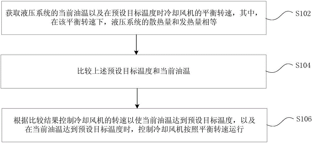
[0026] figure 1 It is a flowchart of a method for controlling the rotation speed of a cooling fan in a hydraulic system according to an embodiment of the present invention. Such as figure 1 As shown, the method includes steps S102-S106:

[0027] Step S102: Obtain the current oil temperature of the hydraulic system and the balance rotation speed of the cooling fan at the preset target temperature, where the heat dissipation and heat generation of the hydraulic system are equal at the balance rotation speed. In other words, at this equilibrium speed, the hydraulic system is in thermal equilibrium. The thermal equilibrium state means that the heat generated by the hydraulic system is equal ...


PUM


Abstract

The invention provides a rotating speed control method and a rotating speed control device for a cooling fan in a hydraulic system. The method comprises the following steps of acquiring current oil temperature of the hydraulic system and a balanced rotating speed of the cooling fan at preset target temperature, wherein at the balanced rotating speed, the heat dissipation amount of the hydraulic system is equal to the heating amount of the hydraulic system; comparing the preset target temperature and the current oil temperature; controlling the rotating speed of the cooling fan according to a comparison result to enable the current oil temperature to reach the preset target temperature; when the current oil temperature reaches the preset target temperature, controlling the cooling fan to run according to the balanced rotating speed. According to the technical scheme provided by the invention, the problems of electricity loss of a storage battery and waste of energy which are caused by a reason that the cooling fan adopts higher rotating speed in the correlation technique are solved; the cooling fan can be controlled to be run at the balanced rotating speed; the hydraulic system is kept constant at the set temperature; the power consumption of the cooling fan is reasonably used.

Description

Technical field [0001] The invention relates to the field of heat dissipation of hydraulic systems, and in particular to a method and device for controlling the rotation speed of a cooling fan in a hydraulic system. Background technique [0002] As the key equipment in construction, most construction machinery often have to work for a long time in harsh environments. Because they often work for a long time in high-temperature environments with heavy loads, the hydraulic system oil temperature will be too high during work, so In order to meet the heat dissipation needs of the hydraulic oil, the cooling fans used to cool the hydraulic system are operated at a constant speed to ensure that the entire hydraulic system is cooled by cooling air under any working conditions. But this will cause excess cooling capacity in winter, waste energy, and increase operating costs. In summer, there may be phenomena such as insufficient cooling capacity and excessively high hydraulic oil temperat...

Claims


Application Information

Patent Timeline
Patent Type & Authority Patents(China)
IPC IPC(8): F15B21/04F04D27/00
Inventor 曾中炜
Owner ZOOMLION HEAVY IND CO LTD
Why Eureka
Try Eureka