A kind of hollow interlayer tube wall ribbed composite steel tube concrete wind power tower

A technology of steel pipe concrete and interlayer, which is applied in the direction of towers, building types, buildings, etc., can solve the problems of local buckling of pipe walls, reduce the bearing capacity of components, etc., achieve enhanced interface cohesion, improve earthquake resistance, and facilitate processing and manufacturing Effect

Active Publication Date: 2015-12-30
博菱(苏州)科技有限公司
View PDF5 Cites 1 Cited by
  • Summary
  • Abstract
  • Description
  • Claims
  • Application Information

AI Technical Summary

Problems solved by technology

[0004] Although the hollow sandwich compound concrete-filled steel tube member has improved material properties and mechanical properties compared with steel members or concrete members, when the steel pipe wall is thinner, the pipe wall is prone to local buckling under the action of pressure. , which reduces the bearing capacity of the member

Method used


Image

  • A kind of hollow interlayer tube wall ribbed composite steel tube concrete wind power tower
  • A kind of hollow interlayer tube wall ribbed composite steel tube concrete wind power tower
  • A kind of hollow interlayer tube wall ribbed composite steel tube concrete wind power tower

Examples


Embodiment 1

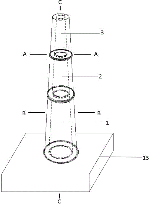
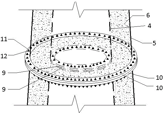
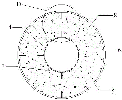
[0028] Embodiment 1: A kind of hollow interlayer pipe wall ribbed composite steel pipe concrete wind power tower, such as figure 1 As shown, including cast-in-place reinforced concrete foundation 13, three-section concrete-filled steel pipe tower section 1; 2; 3, as image 3 As shown, each steel pipe concrete tower section 1; 2; 3 includes the inner steel pipe 4, the outer steel pipe 5 and the concrete layer 6 poured between the inner steel pipe 4 and the outer steel pipe 5, and the thickness of the inner steel pipe 4 and the outer steel pipe 5 is 25mm , the cross sections are all circular, not prone to buckling, and have good and stable bearing capacity. The outer wall of the inner steel pipe 4 in contact with the concrete layer 6 is evenly welded with eight first stiffeners 7, and the outer steel pipe 5 is in contact with the concrete layer 6. There are eight second stiffeners 8 uniformly welded around the inner wall of the inner wall, the stiffener cross-sections are all re...

Embodiment 2

[0031] Embodiment 2: roughly the same as Embodiment 1, the difference is that the cross-section of the inner steel pipe 4 is a square, and the cross-section of the outer steel pipe 5 is circular, as Figure 6 As shown, two first stiffeners 7 are arranged symmetrically on each side of the inner steel pipe 4 to ensure the bonding force between each side of the square steel pipe and the concrete, so that the inner steel pipe 4 and the concrete layer 6 are tightly bonded and local buckling is not easy to occur. Improve the bearing capacity of the tower; such as Figure 7 As shown, the diameter of the outer steel pipe 5 gradually decreases from bottom to top to form a taper.

Embodiment 3

[0032] Embodiment 3: as Figure 8 As shown, it is roughly the same as Example 1, except that the cross section of the inner steel pipe 4 is a regular hexagon, and a first stiffener 7 is arranged on each side of the regular hexagon, so the inner steel pipe 4 is divided into six directions on average. Make the first stiffener 7 go deep into the concrete layer 6, and firmly bond with the concrete to enhance the cohesive force. At the same time, the regular hexagon can weaken the stress concentration phenomenon at the corners of the inner steel pipe 4, make the stress distribution on the section more uniform, and avoid forming The weak area prevents local buckling of the inner steel pipe 4 and improves the seismic capacity of the tower.


PUM


Abstract

The invention discloses a hollow interlayer pipe wall ribbed composite steel pipe concrete wind power tower, which comprises a cast-in-place reinforced concrete foundation, a group of steel pipe concrete tower sections, and the steel pipe concrete tower sections are connected by horizontal flanges to form a vertical tower. At the same time, the bottom of the tower is fixed on the cast-in-place reinforced concrete foundation. The steel pipe concrete tower section includes the inner steel pipe, the outer steel pipe and the concrete layer poured between the inner steel pipe and the outer steel pipe. The outer wall of the inner steel pipe is provided with a first stiffener. The inner wall of the outer steel pipe is provided with a second stiffener; compared with the existing steel tower, the present invention adopts a composite steel pipe concrete structure with a hollow interlayer and ribs on the pipe wall. Stiffeners enhance the interface bonding force between steel pipe and concrete, improve the bearing capacity and ductility of the tower, and can avoid or delay the premature local buckling failure of thin-walled steel pipes.

Description

technical field [0001] The invention relates to wind power generation equipment, in particular to a wind power tower. Background technique [0002] The tower is the main supporting device in the wind turbine. With the development of the wind turbine, the tower has gone through the forms of single-pipe stay wire, truss stay wire, truss tower and common cone tower. Modern large-scale Wind turbines usually use steel cone towers. The single-unit capacity of wind turbine units continues to increase, and the corresponding towers are also developing towards towering, especially for towers with a height of more than 100 meters. There are some insurmountable problems in transportation, installation and maintenance, which greatly increase the cost of the unit; and with the increase of the height of the tower, the problems of aerodynamics and structural dynamics are more prominent, which affect the strength of the tower, Both stiffness and stability place new demands. [0003] As a ...

Claims


Application Information

Patent Timeline
Patent Type & Authority Patents(China)
IPC IPC(8): E04H12/12
Inventor 蔡新顾荣蓉潘盼朱杰
Owner 博菱(苏州)科技有限公司
Why Eureka
Try Eureka