Variable diameter drill by varying pushing force
A technology of thrust and drill body, which is applied in the field of drilling tools and drilling tools, and can solve problems such as the inability to achieve stable positioning of movable drill bits
- Summary
- Abstract
- Description
- Claims
- Application Information
AI Technical Summary
Problems solved by technology
Method used
Image

Examples
Embodiment 1
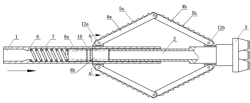
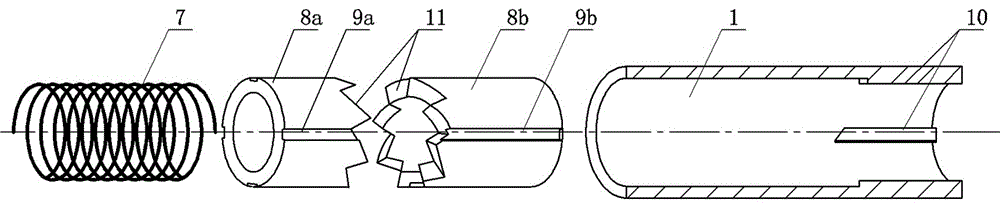
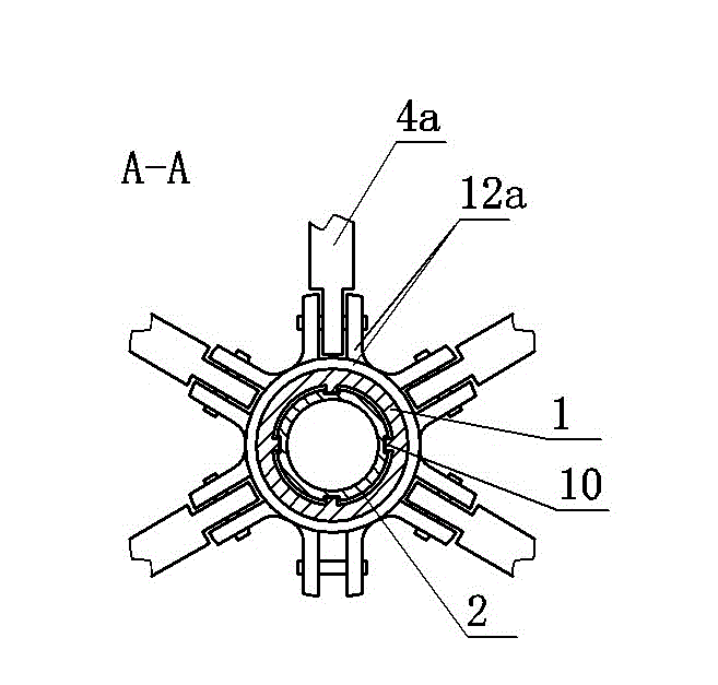
[0016] Embodiment 1: a kind of variable-diameter drill that relies on changing thrust, see figure 1 , the outer drill rod 1 and the inner drill rod 2 are mutually nested, and a structure that can only slide axially is set between the two, such as through a spline fit, or a concave hole that cooperates with the guide rib 10 is set on the outer wall of the inner casing. groove.
[0017] A fixed drill bit 3 is installed on the front end of the inner drill rod 2, and a movable drill bit is arranged between the outer drill rod 1 and the inner drill rod 2.
[0018] figure 1 Among them, the movable drill bit includes multiple sets of drill body 1 4a and drill body 2 4b, and supports 12a and 12b are fixed on the outer sides of the outer drill rod 1 and the inner drill rod 2 respectively. The ends of each group of drill body one 4a and drill body two 4b are respectively hinged on the supports 12a and 12b through pin shafts. The other ends of each group of drill body one 4a and dri...
Embodiment 2
[0021] Embodiment 2: Another variable-diameter drill that relies on changing the thrust. The drawings are not drawn. The content is basically the same as that of the embodiment, and the similarities will not be repeated. The difference is that the inner drill rod is located at the rear end and the outer drill rod is located at the front end. , the fixed drill rod is arranged at the end of the outer drill rod.
PUM
 Abstract
Description
Claims
Application Information
 - Generate Ideas
- Intellectual Property
- Life Sciences
- Materials
- Tech Scout
- Unparalleled Data Quality
- Higher Quality Content
- 60% Fewer Hallucinations
Browse by: Latest US Patents, China's latest patents, Technical Efficacy Thesaurus, Application Domain, Technology Topic, Popular Technical Reports.
© 2025 PatSnap. All rights reserved.Legal|Privacy policy|Modern Slavery Act Transparency Statement|Sitemap|About US| Contact US: help@patsnap.com