
Liquid crystal display device
A technology of a liquid crystal display device and a liquid crystal layer, which is applied in the directions of optics, instruments, nonlinear optics, etc., can solve problems such as crosstalk and deterioration of display characteristics, and achieve the effects of reducing crosstalk, good viewing performance, and good viewing performance
- Summary
- Abstract
- Description
- Claims
- Application Information
AI Technical Summary
Problems solved by technology
Method used
Image

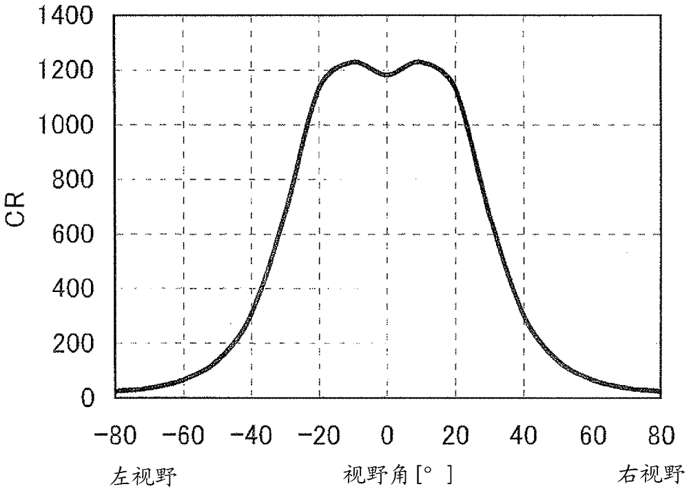
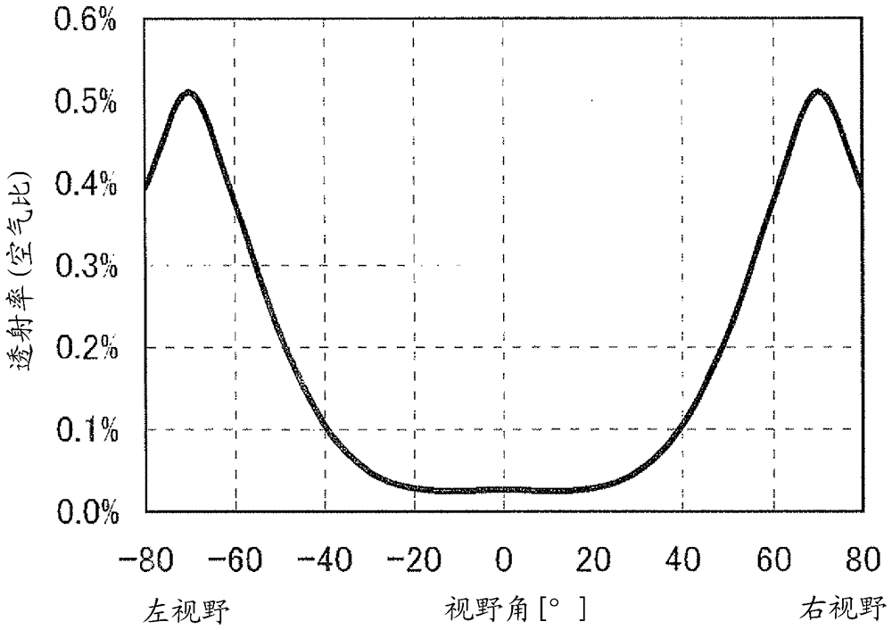
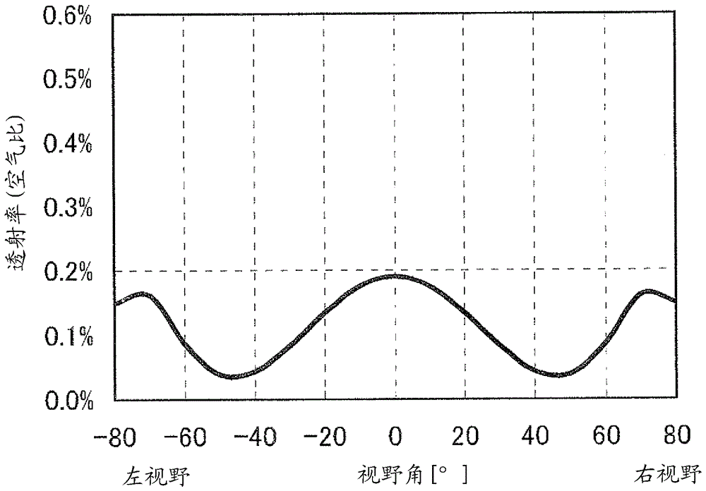
Examples
no. 1 Embodiment approach
[0077] A parallax barrier system multi-screen liquid crystal display device according to a first embodiment of the present invention will be described with reference to the drawings. In this embodiment, a left and right two-screen display will be described as an example. In this embodiment mode, an active matrix liquid crystal display device using TFTs as pixel switching elements will be described as an example.
[0078] figure 1 It is a schematic exploded perspective view of the liquid crystal display device of this embodiment. figure 2 It is a schematic cross-sectional view showing main components of the liquid crystal display device according to the present embodiment. Figure 3A with Figure 3B is a diagram showing an example of a plan view of a parallax barrier layer.
[0079] figure 1 Arrows in , indicate the orientation direction of the liquid crystal layer 105, the absorption axes of the linear polarizers 102a and 102b, and the orientation directions of the vie...
no. 2 Embodiment approach
[0147] A parallax barrier system multi-screen display liquid crystal display device according to a second embodiment of the present invention will be described. Also in this embodiment, a left-right two-screen display device will be described as an example.
[0148] The basic configuration of the liquid crystal display device of this embodiment is the same as that of the first embodiment, and it is a transmissive liquid crystal display device including a backlight (BL) as in the first embodiment. The liquid crystal display device of this embodiment differs from the first embodiment in that the liquid crystal is in a VA (Vertical Alignment) mode in which the liquid crystal is substantially vertically aligned in a state where no electric field is applied.
[0149] In this embodiment, the basic configuration is the same as that of the first embodiment, so it will be described with reference to the drawings and symbols of the first embodiment.
[0150] The VA mode has an advantag...
no. 3 Embodiment approach
[0165] A parallax barrier system multi-screen display liquid crystal display device according to a third embodiment of the present invention will be described. Also in this embodiment, a left-right two-screen display device will be described as an example.
[0166] The basic configuration of the liquid crystal display device of this embodiment is the same as that of the first embodiment, and it is a transmissive liquid crystal display device including a backlight (BL) as in the first embodiment. The difference between the liquid crystal display device of this embodiment and the first embodiment is that it is an IPS (In-Plane Switching in-plane switching) mode or an FFS (Fringe Field Switching) mode of a liquid crystal mode driven by a transverse electric field. model. In these modes, both the pixel electrode and the counter electrode are formed on one substrate side.
[0167] In this embodiment, the basic configuration is the same as that of the first embodiment, so it will ...
PUM
| Property | Measurement | Unit |
|---|---|---|
| angle | aaaaa | aaaaa |
Abstract
Description
Claims
Application Information