Fluid control device

A technology for fluid control devices and fluid control valves, which is applied in the direction of fluid pressure actuators, lifting devices, servo motors, etc., and can solve the problem of unstable operability of operators

Active Publication Date: 2021-08-20
SHIMADZU SEISAKUSHO CO LTD
View PDF6 Cites 0 Cited by
  • Summary
  • Abstract
  • Description
  • Claims
  • Application Information

AI Technical Summary

Problems solved by technology

In the case of such a phenomenon, the operability performed by the operator is not fixed

Method used


Image

  • Fluid control device
  • Fluid control device
  • Fluid control device

Examples


Embodiment Construction

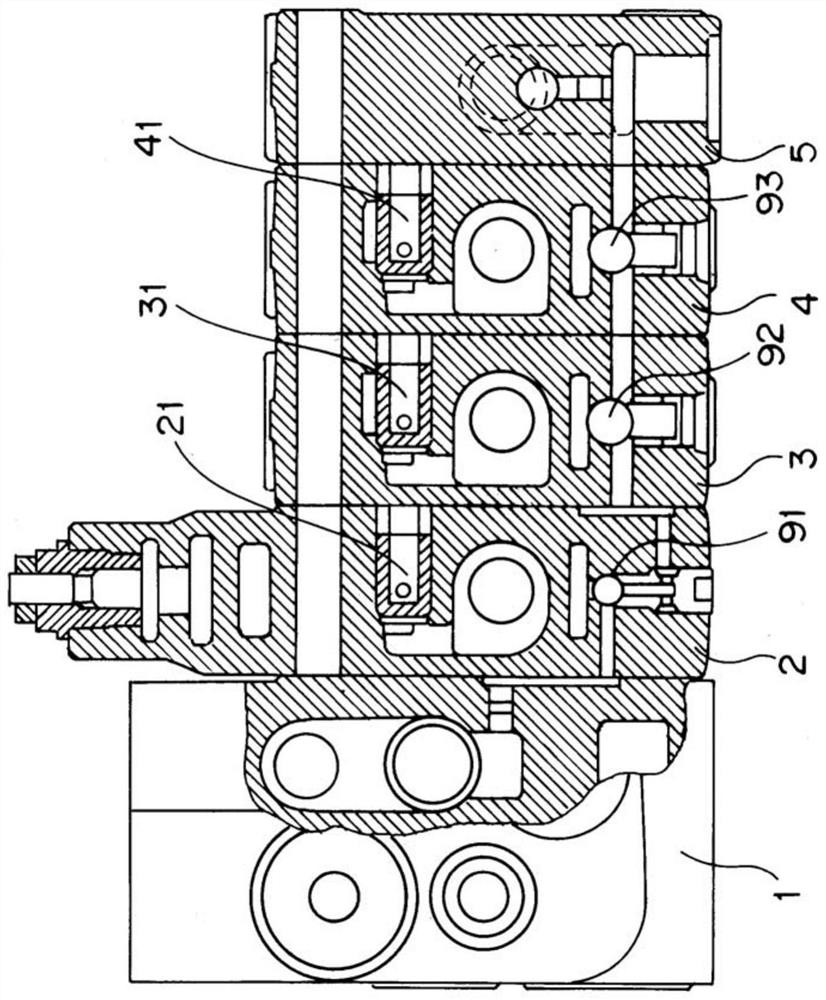
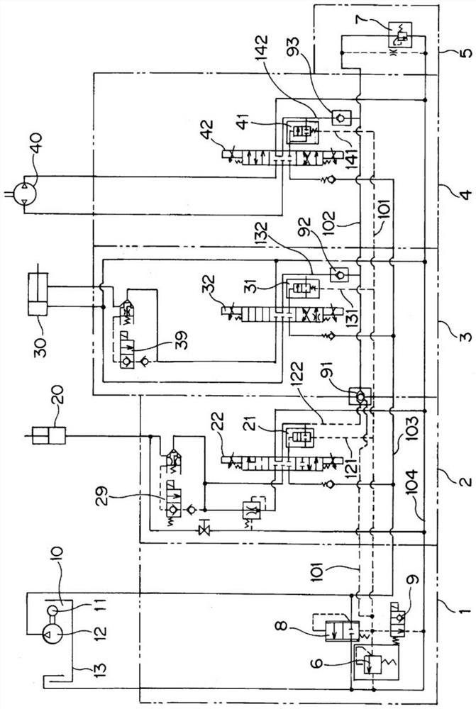
[0025] Hereinafter, embodiments of the present invention will be described based on the drawings. figure 1 It is a schematic longitudinal sectional view of the fluid control device of the present invention. in addition, figure 2 is a hydraulic circuit diagram in the fluid control device of the present invention.

[0026] This fluid control device uses hydraulic oil as the hydraulic fluid and controls the supply of hydraulic oil for each function of the forklift. This fluid control device has the following structure: a front cover 1 for supplying working oil from a hydraulic source 10, a fluid control valve (control valve) 2 for supplying working oil to a lift cylinder 20, and a fluid control valve (control valve) for tilting The cylinder 30 includes a fluid control valve 3 for supplying hydraulic oil, a fluid control valve 4 for supplying hydraulic oil to a rotary drive unit 40 for a rotary attachment, and a rear cover 5 .

[0027] The front cover 1 is connected to a hydra...


PUM


Abstract

During opening and closing operations of a fluid control valve (2), the port pressure in the fluid control valve (2) is guided to a main relief valve (6) via a first passage (101) and the maximum pressure thereof is controlled by the main relief valve (6). In addition, the port pressure in the fluid control valve (2) is simultaneously guided to pressure compensation valves (21), (31), (41) of fluid control valves (2), (3), (4). Thus, even in the case when functions with different load pressures are simultaneously operated in the fluid control valves (2), (3), (4), it is possible always to guarantee constant operability regardless of the pressure load. In addition, during opening and closing operations of the fluid control valve (3) that drives a tilt cylinder (30) for a function to tilt a fork, the port pressure of the fluid control valve (3) is guided to a secondary relief valve (7) via a second passage (102), is guided to the main relief valve (6) via the first passage (101), and is guided to the pressure compensation valves (21), (31), (41) of the fluid control valves (2), (3), (4).

Description

technical field [0001] The present invention relates to a fluid control device of a closed center circuit type having a plurality of fluid control valves. Background technique [0002] In such a fluid control device having a structure in which a plurality of fluid control valves (control valves) are arranged in a row, a relief valve is used in order to prevent an excessive increase in the hydraulic pressure of the working fluid. For example, in a fluid control device used in a forklift, a structure is adopted in which a pressure relief valve corresponding to the maximum pressure is used for an area where the hydraulic pressure of the working fluid such as an elevating function is required to be maximum, and a hydraulic pressure of the working fluid is lower than that. Areas, set pressure relief valves in each area. Therefore, the pressure relief valve is required for each function, and the device is complicated and enlarged, and the cost of the device is increased. [0003...

Claims


Application Information

Patent Timeline
Patent Type & Authority Applications(China)
IPC IPC(8): F15B11/16
CPCF15B2211/3111B66F9/22F15B2211/30555F15B2211/6055F15B2211/6054F15B11/163B66F9/16F15B2211/20538F15B2211/30515F15B2211/50536F15B2211/6052
Inventor 丹羽宙润
Owner SHIMADZU SEISAKUSHO CO LTD
Why Eureka
Try Eureka