High-frequency power supply device, plasma processing device and method for producing thin film

A high-frequency power and supply device technology, applied in plasma, semiconductor/solid-state device manufacturing, circuits, etc., can solve problems that cannot be achieved and are difficult to solve

Inactive Publication Date: 2015-03-25
MITSUBISHI ELECTRIC CORP
View PDF7 Cites 0 Cited by
  • Summary
  • Abstract
  • Description
  • Claims
  • Application Information

AI Technical Summary

Problems solved by technology

On the other hand, when it is about 100cm×100cm, it becomes about ±20 to 40%, and there is a problem that the above-mentioned index cannot be achieved.
[0008] The formation of standing waves is caused by basic physical phenomena such as wave interference, so it is very difficult to fundamentally solve

Method used


Image

  • High-frequency power supply device, plasma processing device and method for producing thin film
  • High-frequency power supply device, plasma processing device and method for producing thin film
  • High-frequency power supply device, plasma processing device and method for producing thin film

Examples


Embodiment approach 1

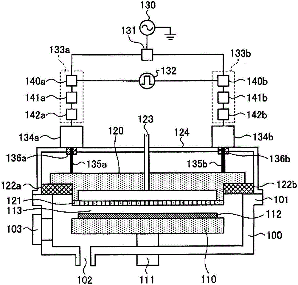
[0059] figure 1 It is a diagram schematically showing a configuration example of Embodiment 1 of the plasma processing apparatus of the present invention. Such as figure 1 As shown, the plasma processing apparatus of this embodiment is a plasma processing apparatus that generates plasma and forms a thin film by chemical vapor deposition, and includes a vacuum chamber 100, a stage 110 with a moving mechanism, and a plurality of gas supply ports. Shower plate 121, pulse generator (power switching unit) 132, high-frequency power sources (power sources) 133a and 133b capable of pulse modulation.

[0060] The vacuum chamber 100 is connected to the flange 101 and is airtightly sealed with the insulating gaskets 122a and 122b to separate the interior from the atmosphere. The insulating spacers 122a, 122b fix the electrode block 120 . These structures constitute a decompression container including a stage 110 and a shower plate 121 inside, and the space between the stage 110 and th...

Embodiment approach 2

[0125] In Embodiment 1, the number of feeding points is 2 for description, but in the method suggested by the present invention, the number of feeding points may be greater than or equal to 2. Hereinafter, as another embodiment, a case where the number of feeding points is 4 or more will be described as an example of feeding at 2 or more points. The structure of the plasma processing apparatus of the present embodiment is different from the number of feed points (that is, four sets of high-frequency power supplies, matching devices, and feed rods are provided, and the pulse generator (power switching unit) 132 is used for supplying four high-frequency power supplies. The configuration is the same as that of Embodiment 1 except for the switched output signal). In addition, for the sake of simplicity, four points are set, and when the number of feeding points is greater than or equal to 3 or greater than or equal to 5, it can also be expanded according to the same thinking metho...


PUM


Abstract

A high-frequency power supply device for supplying high-frequency power to parallel planar electrodes, the high-frequency power supply device comprising: high-frequency power sources (133a, 133b) for supplying high-frequency power to positions spaced apart from each other in the electrode; and a pulse generator for pulse-modulating the power supplied from the high-frequency power sources (133a, 133b) such that the power changes at a plurality of levels including a high level and a low level, the pulse generator instructing switching of levels to include a period (1) during which the supplied power from the high-frequency power source (133a) is at the high level and the supplied power from the high-frequency power source (133b) is at the low level, a period (2) during which the supplied power from the high-frequency power source (133b) is at the high level and the supplied power from the high-frequency power source (133a) is at the low level, and a period (3) during which the supplied power from each of the high-frequency power sources (133a, 133b) is at a level higher than the low level.

Description

technical field [0001] The present invention relates to a high-frequency power supply device, a plasma processing device, and a thin film manufacturing method. Background technique [0002] Plasma film forming apparatuses are widely used as apparatuses for forming thin films such as amorphous silicon thin films and microcrystalline silicon thin films on substrates. Currently, a plasma film-forming apparatus capable of forming a large-area thin film such as a thin-film transistor used in a power generation layer of a thin-film silicon solar cell or a flat-panel display at a high speed at one time is being developed. In order to form a large-area silicon thin film, a parallel-plate type plasma film-forming apparatus is generally used. [0003] The parallel plate type plasma film forming apparatus has a first electrode and a second electrode facing each other at a distance of several mm to several tens of mm in a vacuum chamber. Normally, the electrodes are arranged in a hori...

Claims


Application Information

Patent Timeline
Patent Type & Authority Patents(China)
IPC IPC(8): H05H1/46C23C16/515H01L21/205H01L21/265H01L21/3065
CPCH01J37/32137C23C16/24H01J37/32146H05H2001/4682H01J37/32577H01J37/32174H01J37/32091H05H1/46C23C16/517H05H2242/26
Inventor 池田知弘滝正和津田睦藤原伸夫
Owner MITSUBISHI ELECTRIC CORP
Why Eureka
Try Eureka