
Steering shaft device

A technology for steering devices and steering shafts, applied to steering columns, steering controls mounted on vehicles, couplings, etc., can solve problems such as difficult to see connecting parts, small room for movement, and difficulties for assembly workers

Active Publication Date: 2016-10-12
MERCEDES BENZ GRP
View PDF9 Cites 0 Cited by
  • Summary
  • Abstract
  • Description
  • Claims
  • Application Information

AI Technical Summary

Problems solved by technology

This is extremely difficult for the assembler, since the construction space for manual handling only allows little room for movement and the connection kit is not easily seen visually

Method used


Image

  • Steering shaft device
  • Steering shaft device
  • Steering shaft device

Examples


Embodiment Construction

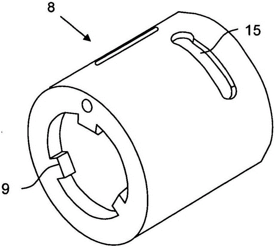
[0030] The device according to the invention is a steering device which has an intermediate part in the form of a hub which connects the fork of the steering coupling with the steering shaft connection.

[0031] exist Figure 4 An embodiment of such a steering device 1 can be seen in FIG. The opposite ends of the intermediate piece 3 and the steering shaft connection 2 of the steering shaft are formed as plug-in fittings, which have guide elements 5, 6 cooperating with each other (cf. figure 1 and image 3 ) and provide forced guidance of the transmitted torque. In addition, the steering device 1 also provides a clamping device, by means of which the plug-in parts can be clamped together in the plugged position, and the clamping device Figure 4 This is achieved by means of a helical spring 7 which enables a play-free connection.

[0032] Based on figure 1 and 3 The guide elements shown as grooves 5 and tenons 6 in the example are easily touched or visually perceived by ...


PUM


Abstract

The invention provides a steering device (1), which has a steering shaft, the steering shaft has a steering shaft connecting portion (2), and the steering shaft connecting portion is connected to a fork (4) of a steering coupling device through an intermediate piece (3) )connect. The steering shaft connection ( 2 ) and the hub-shaped intermediate part ( 3 ) are provided at the ends facing each other by means of at least one tongue-and-groove guide element pair ( 5 , 6 ) oriented in the longitudinal direction. ) is formed as a plug-in fitting, the tongue-and-groove guide pair provides a positive guidance for the transmitted torque. This is achieved in that the first guide element of the guide element pair (5, 6) is arranged on the steering shaft connection (2) and the second guide element is arranged on the intermediate part (3), wherein the upper The tightening device tightens the plug-in mating parts to each other in the plug-in position.

Description

technical field [0001] The invention relates to a steering shaft arrangement of a motor vehicle at the interface between the steering shaft and the steering coupling. Background technique [0002] The direct screw connection of the steering shaft underneath to the steering coupling, which has been implemented until now, can only be realized with considerable effort in the packaging environment from the exhaust system, catalytic converter, engine and lines. In this case, the steering shaft is screwed to the steering coupling at the bottom transversely to the direction of the steering shaft. On the one hand this has the disadvantage of poor accessibility, on the other hand it increases the number of variants when optimizing the accessibility for different engine variants and steering positions (e.g. left-hand drive versus right-hand drive), and very little Or it may not even be possible to observe standard installation sequences at all, such as when the exhaust system is inst...

Claims


Application Information

Patent Timeline
Patent Type & Authority Patents(China)
IPC IPC(8): B62D1/20F16D1/08F16D3/38
CPCB62D1/20F16D1/0876F16D1/0882F16D1/0888F16D3/387Y10T403/7062Y10T403/7066F16D1/08
Inventor A·赫本斯特雷特H-D·勒夫勒T·迈尔
Owner MERCEDES BENZ GRP
Learn More