
Cap feeding apparatus and method

A technology of a supply device and a filling machine, which is applied in the field of cap supply, can solve the problems of easy failure, additional cost, damaged caps, etc., and achieves the effect of less failure and less maintenance.

Active Publication Date: 2016-03-23
KRONES AG
View PDF7 Cites 0 Cited by
  • Summary
  • Abstract
  • Description
  • Claims
  • Application Information

AI Technical Summary

Problems solved by technology

However, this solution has the disadvantage that the ejected cap has to be removed or the device resupplied, which requires additional work steps and entails additional costs
[0009] In addition, the two prior art solutions have the disadvantage of providing cost-inducing additional devices, which must be maintained and cleaned
Stoppers in particular are prone to failure in corrosive applications and can damage the cover if set incorrectly

Method used


Image

  • Cap feeding apparatus and method
  • Cap feeding apparatus and method
  • Cap feeding apparatus and method

Examples


Embodiment Construction

[0041] Preferred embodiments are described below in conjunction with the accompanying drawings. Here, identical, similar or identically acting elements are identified with the same reference numerals and a repeated description of these elements is omitted in the following description in order to avoid redundancy.

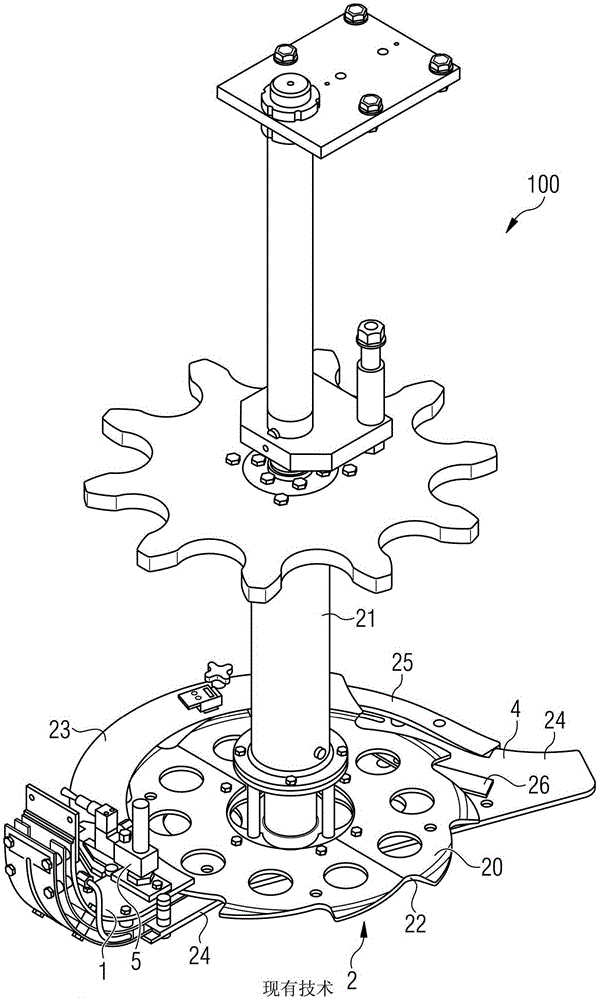
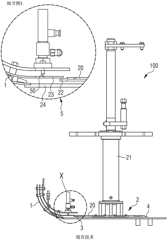
[0042] figure 1 A device 100 according to the prior art is shown schematically in a perspective view for supplying caps not shown here. figure 2 A schematic side view of the device 100 according to the prior art is shown.

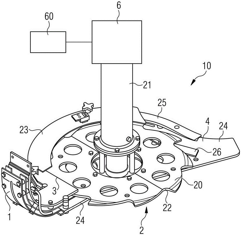
[0043] figure 1 and figure 2 The illustrated cap supply device 100 comprises a supply unit 1 for continuously supplying caps to a take-up wheel 2 . The supply unit 1 is designed as a cap supply chute, through which a certain stagnation pressure is brought to the caps, and then the caps are supplied to the receiving wheel 2 .

[0044] The take-up wheel 2 has a disc-shaped body 20 and is driven by a drive shaft 21 . On the periphery of the ...


PUM


Abstract

The device (10) has pick wheel (2) having pocket (22) to take away a closure of driving position to transfer position for transferring the closure to capping carousel. The pick wheel forms device for the interruption of the closure feed to the capping carousel. An independent claim is included for method for supplying closure.

Description

technical field [0001] The present invention relates to a cap supply device for supplying caps, preferably screw caps, to a plugging head in a sealer carousel of a beverage filling machine for supplying caps, and to a cap supplying method . Background technique [0002] It is already known to close containers, such as bottles, with different closure devices which are adapted to various types of caps. Devices are known which press and tap the cork or stopper into the mouth of the bottle. Other known devices press the crown cork onto the corresponding bottle mouth, while other known devices are used to apply rolled caps, where the bottle mouth already has an external thread, and the corresponding rolled Roller cappers of side rolls are rolled onto this external thread. Furthermore, thread sealers are also known, in which a plastic screw cap is generally screwed onto a plastic bottle finish which is also provided with an external thread. [0003] To feed the caps to the clo...

Claims


Application Information

Patent Timeline
Patent Type & Authority Patents(China)
IPC IPC(8): B67B3/062
CPCB67B3/06
Inventor 卢茨·肯姆普曼
Owner KRONES AG
Learn More