Device and method for implementing and monitoring a laser transmission welding process of plastics

A laser transmission welding and process technology, applied in laser welding equipment, measuring devices, welding equipment, etc., can solve the problem of workpiece rejection, no more detailed description of the welding seam, etc.

Inactive Publication Date: 2016-08-17
LPKF LASER & ELECTRONICS
View PDF7 Cites 0 Cited by
  • Summary
  • Abstract
  • Description
  • Claims
  • Application Information

AI Technical Summary

Problems solved by technology

[0005] This existing monitoring method implemented on welds only allows the determination of disturbances in the detected reflected measurement beam caused by imperfections in the weld, which are believed to cause reactions
This type of response may result in the rejection of an artifact determined to be defective
A more detailed account of welds is not provided in this monitoring method

Method used


Image

  • Device and method for implementing and monitoring a laser transmission welding process of plastics
  • Device and method for implementing and monitoring a laser transmission welding process of plastics
  • Device and method for implementing and monitoring a laser transmission welding process of plastics

Examples


Embodiment Construction

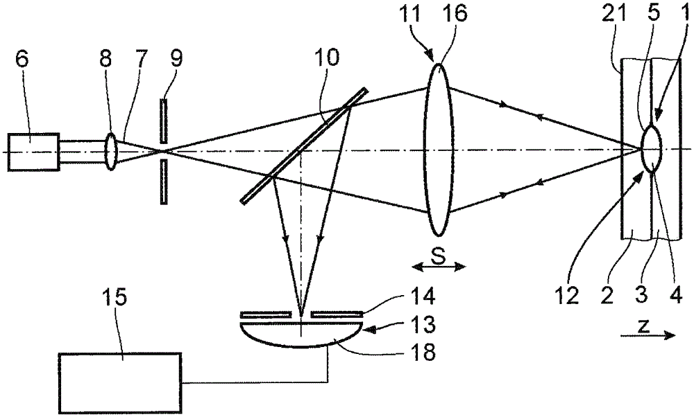
[0024] figure 1 A first embodiment of a device for carrying out and monitoring a plastic laser transmission welding process is shown. The process beam source for generating and emitting a laser beam which is used as a process beam entering the joining region 1 of the two joining elements 2, 3 is not shown in more detail, since it corresponds to the Process beam source used in traditional laser transmission welding. The process beam source is used to form a weld seam 4 between two joining elements 2, 3, as in the figure 1 Between the two joining elements 2, 3 is shown in a cross-sectional view.

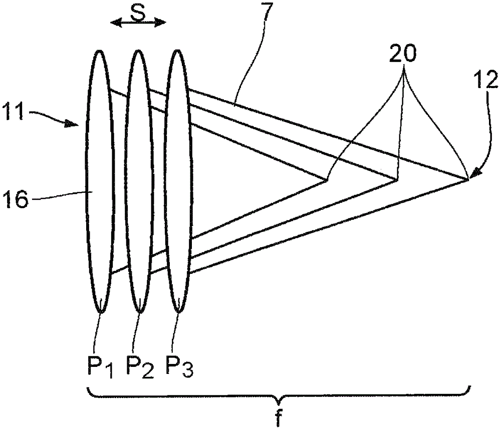
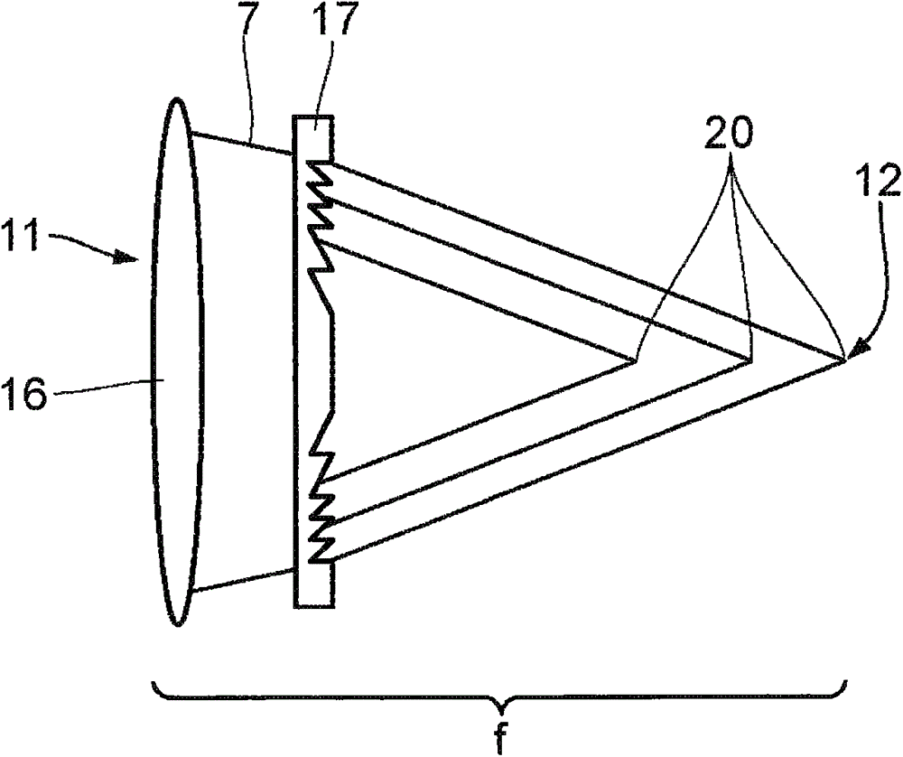
[0025] In order to determine the depth position of the interface 5 between the weld seam 4 and the joining elements 2, 3, in other words for welding depth monitoring in the corresponding laser transmission welding process, a measuring beam source 6 in the form of a point light source is provided, which The measuring beam 7 is processed by a lens 8 and an aperture 9 to obtain a focus...


PUM


Abstract

The invention relates to a device and a method for carrying out and monitoring a process of laser transmission welding of plastics, comprising: a process beam source for emitting a process beam into a joining area (1) between two joining elements (2, 3) ) to form a weld (4); a measuring beam source (6), which irradiates the measuring region (12) with a measuring beam (7); a detection unit (13), which is used to detect The measurement beam (7) reflected by the interface (5) between the weld seam (4) and its surrounding area; and the evaluation unit (15), which is connected to the detection unit (13), for being reflected by the detected A measuring beam (7) is used to determine the depth position of the interface (5) within the joining element (2, 3).

Description

technical field [0001] The present invention relates to a device and a method for carrying out and monitoring a process of laser transmission welding of plastics, said device comprising: - a process beam source for emitting a process beam into the joint area between two joint elements so that Forming the weld seam; - a measuring beam source, which irradiates the measuring region with a measuring beam; and - a detection unit, which is used to detect the measurement reflected by the interface between the welding seam and its surrounding area in the joining element beam. The method comprises the steps of: - arranging a transmissive joining element and an absorptive joining element in the joining position; - irradiating the joining element with a process beam in the joining region to form a weld seam, and irradiating the welding seam with a measuring beam and - detecting by the detection unit the measurement beam reflected by the interface between the weld seam and its surroundin...

Claims


Application Information

Patent Timeline
Patent Type & Authority Patents(China)
IPC IPC(8): B29C65/16B29C65/82G01N21/17G01N21/958
CPCB29C65/1638B29C65/1654B29C65/1674B29C66/1122B29C66/41B29C66/836B29C66/952B29C65/8253B23K26/0648B29C66/91216B23K31/125G01J5/0014B29C66/91411B29C65/1635B29C66/961B29C66/9161B29C65/00G01J5/48B29C65/16
Inventor M·西本D·赫特勒
Owner LPKF LASER & ELECTRONICS
Why Eureka
Try Eureka