
Wireless control method and system for electronic door lock

An electronic door lock, wireless control technology, applied in the direction of instruments, time register, single input port/output port register, etc., can solve the problems of difficult wiring, increase production cost, high system cost, etc., to improve standby time Effect

Active Publication Date: 2017-01-18
SHENZHEN LOCSTAR TECH
View PDF5 Cites 0 Cited by
  • Summary
  • Abstract
  • Description
  • Claims
  • Application Information

AI Technical Summary

Problems solved by technology

Among them, the door lock system based on the traditional video doorbell has the following defects: 1) The outdoor image can only be displayed on the indoor image display device, which is only suitable for indoor users; 2) The locking mechanism is controlled by the outdoor unit through wired methods. If the outdoor unit is damaged or fails, the access control function will also fail, and the reliability of the system is poor.
The door lock system based on building video intercom technology has the following defects: this type of doorbell system needs to be connected to the cloud server by wire, the system cost is high, and the wiring is too complicated
This kind of door lock system has the following defects: 1) The power consumption of the wireless communication module is relatively high; if the door lock system adopts a battery-powered power supply solution, the door lock system can only work in the doorbell induction trigger mode, and the system function is severely affected. If the door lock system uses an external power supply power supply solution, it will cause a new problem of difficult wiring; 2) The technical content of the built-in wireless communication module in the door lock is high; 3) Due to the wide variety of door locks, For manufacturers, developing special door lock products with built-in wireless communication modules for different types of door locks will greatly increase production costs

Method used


Image

  • Wireless control method and system for electronic door lock
  • Wireless control method and system for electronic door lock
  • Wireless control method and system for electronic door lock

Examples


Embodiment Construction

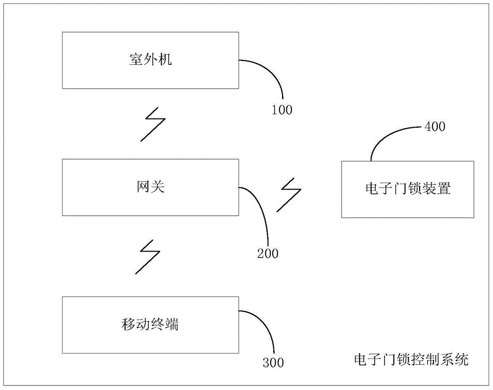
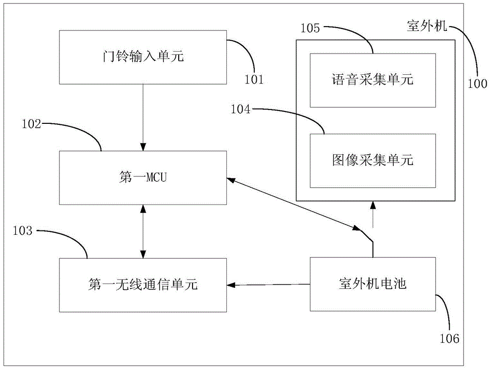
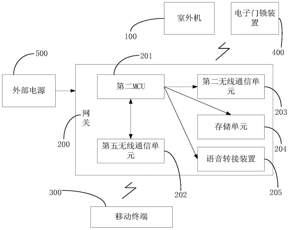
[0058] In order to solve the problem of complex wiring of the wired door lock control system in the prior art, high system construction and maintenance costs, and limited use range indoors, or the wireless door lock system is limited by the high power consumption of the built-in wireless communication module, resulting in incomplete system functions The main innovations of the present invention are: 1) Establish wireless communication between the outdoor unit 100 / door lock device, the gateway 200 and the mobile terminal 300, and use the gateway 200 as the link between the outdoor unit 100 / door lock device and the mobile terminal 300 2) Both the outdoor unit 100 and the electronic door lock device 400 work in an interval sleep mode to reduce power consumption; the first MCU102 of the outdoor unit 100 and the second MCU201 of the electronic door lock device 400 are in an idle state Automatic sleep; the lock control mechanism 403 adopts a passive working mode; 3) The gateway 200 c...


PUM


Abstract

The invention discloses a wireless control method and system of an electronic lock. The wireless control system comprises an outdoor unit (100), an electronic lock device (400), an indoor gateway (200) and at least one mobile terminal (300), wherein the outdoor unit (100) is used for generating doorbell trigger information when the doorbell trigger operation is detected in the work period of the outdoor unit (100), starting an image acquisition unit (104) to acquire an outdoor image, and transmitting the doorbell trigger information and the outdoor image into the gateway (200) by a wireless network; the gateway (200) is used for transmitting the doorbell trigger information and the outdoor image into the mobile terminal (300) for displaying; the mobile terminal (300) is used for generating a related lock control command according to the input of a user, and transmitting the lock control command into the electronic lock device (400) by the gateway (200); the electronic lock device (400) is also used for controlling a lock control mechanism (403) to lock and unlock according to the lock control command.

Description

technical field [0001] The present invention relates to the field of smart home informatization, and more specifically, to a wireless control method and system for electronic door locks. Background technique [0002] At present, the popular door lock systems with visual functions on the market are mainly divided into the following two types: [0003] 1. Door lock system based on traditional video doorbell or building video intercom technology. This kind of door lock system generally includes an outdoor unit and an indoor unit that communicate in a wired or wireless manner. The outdoor unit is used to directly control the locking mechanism through wired methods. The indoor unit is used to display the outdoor image or transmit the outdoor image to an indoor image display device for display. Among them, the door lock system based on the traditional video doorbell has the following defects: 1) The outdoor image can only be displayed on the indoor image display device, which i...

Claims


Application Information

Patent Timeline
Patent Type & Authority Patents(China)
IPC IPC(8): G07C9/00
Inventor 彭爱民
Owner SHENZHEN LOCSTAR TECH
Learn More