Threaded sleeve clutch

A clutch and threaded sleeve technology, applied in the field of threaded sleeve clutches, can solve the problems of improved transmission efficiency, low power transmission efficiency, and difficult separation of gears.

Active Publication Date: 2015-12-09
南通盛净环保设备有限公司
View PDF6 Cites 0 Cited by
  • Summary
  • Abstract
  • Description
  • Claims
  • Application Information

AI Technical Summary

Problems solved by technology

[0002] Today's automobile clutches include friction clutches, fluid couplings, and electromagnetic clutches. They all use soft contact, that is, friction, hydraulic force, or electromagnetic force, to transmit the rotational power of the engine. The power transmission efficiency of these soft contacts is relatively high. Low; the reason why the modern developed automobile industry still uses the soft contact clutch method with low power transmission efficiency is because the meshed gears are difficult to separate when the gear meshing transmission rotates at high speed, and no hard transmission that is easy to mesh has not been found yet. The gears are separated and the gear meshing transmission method that can have higher transmission efficiency is a difficult problem in improving the transmission efficiency of automobiles.

Method used


Image

  • Threaded sleeve clutch
  • Threaded sleeve clutch
  • Threaded sleeve clutch

Examples


Embodiment Construction

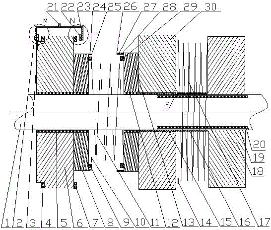
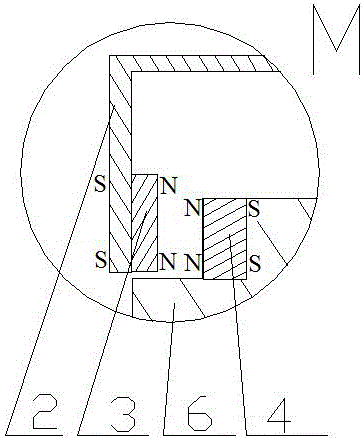
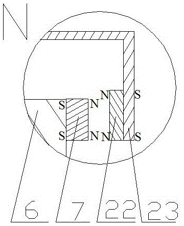
[0023] exist figure 1 In the embodiment shown in -8: the threaded sleeve clutch includes a group of driving wheels and a group of driven wheels adjacent to the driving wheels and a group of driven wheels adjacent to the driven wheels, and the driving wheels include active Wheel 6 and driving wheel secondary wheel 8, driven wheel group comprises driven wheel 30 and driven wheel secondary wheel 13, driven wheel group comprises driven wheel 18 and driven wheel rotation axle sleeve 20, driving wheel 6, driving wheel secondary wheel 8, driven wheel 30 1, driven wheel auxiliary wheel 13, driven wheel 18, driven wheel shaft sleeve 20, driven wheel spring 11, driven wheel spring 17 are all set on the same fixed shaft 1, and are coaxial with the fixed shaft 1; it is characterized in that: active A driven wheel spring 11 is arranged between the wheel 6 and the driven wheel 30, a driven wheel spring 17 is arranged between the driven wheel 30 and the driven wheel 18, the driving wheel 6 i...


PUM


Abstract

A thread cup joint clutch comprises a driving wheel set, a driven wheel set adjacent to the driving wheel set and a passive wheel set adjacent to the driven wheel set. The driving wheel set comprises a driving wheel and an auxiliary driving wheel; the driven wheel set comprises a driven wheel and an auxiliary driven wheel; the passive wheel set comprises a passive wheel and a passive wheel rotating shaft sleeve; the driving wheel, the auxiliary driving wheel, the driven wheel, the auxiliary driven wheel, the passive wheel, the passive wheel rotating shaft sleeve, a driven wheel spring and a passive wheel spring are all arranged on the same fixing shaft in a sleeved mode and are concentric with the fixing shaft. The thread cup joint clutch is characterized in that the driven wheel spring is arranged between the driving wheel and the driven wheel, the passive wheel spring is arranged between the driven wheel and the passive wheel, the driving wheel is a power input wheel, the passive wheel is a power output wheel, the driven wheel is a buffer meshing wheel between the driving wheel and the passive wheel and is provided with internal threads, the passive wheel rotating shaft sleeve are sleeved with external threads, and the internal threads of the driven wheel are matched with the external threads of the passive wheel rotating shaft sleeve.

Description

technical field [0001] The invention relates to a threaded sleeve clutch, which is suitable for various mechanisms requiring clutch speed change and clutch speed regulation, such as clutch speed changers of various vehicles, gearboxes of lathes, etc., and belongs to the technical field of clutch and gear transmission. Background technique [0002] Today's automobile clutches include friction clutches, fluid couplings, and electromagnetic clutches. They all use soft contact, that is, friction, hydraulic force, or electromagnetic force, to transmit the rotational power of the engine. The power transmission efficiency of these soft contacts is relatively high. Low; the reason why the modern developed automobile industry still uses the soft contact clutch method with low power transmission efficiency is because the meshed gears are difficult to separate when the gear meshing transmission rotates at high speed, and no hard transmission that is easy to mesh has not been found yet. ...

Claims


Application Information

Patent Timeline
Patent Type & Authority Patents(China)
IPC IPC(8): F16D43/04
Inventor 魏伯卿
Owner 南通盛净环保设备有限公司
Why Eureka
Try Eureka