Compression spring type buffer friction gear meshing clutch

A technology of friction gears and clutches, which is applied in the field of compression spring buffer friction gear meshing clutches, which can solve the problems of difficult separation of gears, wide structure, low power transmission efficiency, etc.

Active Publication Date: 2016-02-24
贵阳渝冠技术服务中心
View PDF7 Cites 0 Cited by
  • Summary
  • Abstract
  • Description
  • Claims
  • Application Information

AI Technical Summary

Problems solved by technology

[0002] Today's automobile clutches include friction clutches, hydraulic couplings, and electromagnetic clutches. They all use soft contact, that is, friction, hydraulic force, or electromagnetic force, to transmit the rotational power of the engine. The power transmission efficiency of these soft contacts is relatively high. Low; the reason why the modern developed automobile industry still uses the soft contact clutch method with low power transmission efficiency is because the meshed gears are difficult to separate when the gear meshing transmission rotates at high speed, and no hard transmission that is easy to mesh has not been found yet. The gear separation and gear meshing transmission method with higher transmission efficiency is a difficult problem in improving the transmission efficiency of automobiles; although Wei Boqing's invention patent "201410151795.6 Threaded Sleeve Clutch" can achieve high-efficiency transmission of gear clutch meshing, but its There is an intermediate driven wheel with a relatively wide structure and relatively large volume, and the clutching process in Wei Boqing's other invention "201410162087.2 Spring Pressure Friction Gear Engagement Clutch" also has a certain frictional impact effect. The effect of compression, twisting and buffering realizes the high-efficiency transmission structure of gear clutch meshing with small clutch impact

Method used


Image

  • Compression spring type buffer friction gear meshing clutch
  • Compression spring type buffer friction gear meshing clutch
  • Compression spring type buffer friction gear meshing clutch

Examples


Embodiment approach

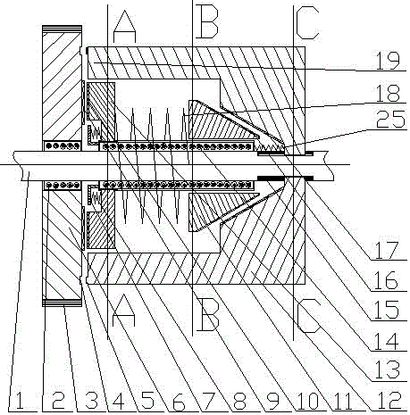
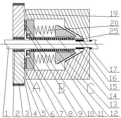
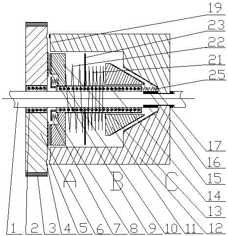
[0026] The driven wheel group comprises a long bearing 14, and a left driven wheel 13 installed on the long bearing 14, a right driven wheel 11, a left driven wheel left spring 8, and a gap between the left driven wheel 13 and the right driven wheel 11 Spring, the spring between the left driven wheel 13 and the right driven wheel 11 has three implementations: Option 1: a large spring 18 is installed between the left driven wheel 13 and the right driven wheel 11, and the large spring 18 is sleeved on the outside of the drive shaft 1 The outer side of the long bearing 14 is not in contact with the outer wall of the long bearing 14, but the central axis of the spring circle of the large spring 18 overlaps with the axis line of the long bearing 14, and the left end of the large spring 18 is fixed on the right side of the left driven wheel 13, and the large spring 18 The right end is fixed on the left side of the right driven wheel 11; Option two: between the left driven wheel 13 an...


PUM


Abstract

A compressed spring type buffer friction gear meshed clutch comprises a driving shaft, a driving wheel, a driven wheel and a set of engaged wheels, wherein the driving shaft is sleeved with the driving wheel, the driven wheel and the engaged wheels, and the engaged wheels are arranged between the driving wheel and the driven wheel. The clutch is characterized in that the engaged wheel set comprises a long bearing, a left engaged wheel, a right engaged wheel, a left engaged wheel left spring and a spring between the left engaged wheel and the right engaged wheel, wherein the left engaged wheel, the right engaged wheel, the left engaged wheel left spring and the spring are arranged on the long bearing, and the spring between the left engaged wheel and the right engaged wheel is implemented according to three schemes. According to the first scheme, the large spring is arranged between the left engaged wheel and the right engaged wheel; according to the second scheme, a plurality of small springs are arranged between the left engaged wheel and the right engaged wheel, and are symmetrically arranged around the long bearing; according to the third scheme, a spring set composed of a left spring and a right spring is arranged between the left engaged wheel and the right engaged wheel, the left spring and the right spring are arranged in series connection, and the winding directions of the left spring and the right spring are opposite; the long bearing is arranged on the driving shaft, and the long bearing can rotate around the axial line of the driving shaft but cannot move along the axial line of the driving shaft.

Description

technical field [0001] The invention relates to a compression spring type cushioning friction gear meshing clutch, which is suitable for various mechanisms requiring clutch speed change and clutch speed regulation, such as clutch speed change devices of various vehicles, gearboxes of lathes, etc., and belongs to the technical field of clutch and gear transmission. Background technique [0002] Today's automobile clutches include friction clutches, hydraulic couplings, and electromagnetic clutches. They all use soft contact, that is, friction, hydraulic force, or electromagnetic force, to transmit the rotational power of the engine. The power transmission efficiency of these soft contacts is relatively high. Low; the reason why the modern developed automobile industry still uses the soft contact clutch method with low power transmission efficiency is because the meshed gears are difficult to separate when the gear meshing transmission rotates at high speed, and no hard transmi...

Claims


Application Information

Patent Timeline
Patent Type & Authority Patents(China)
IPC IPC(8): F16D23/04F16D13/26
Inventor 魏伯卿
Owner 贵阳渝冠技术服务中心
Why Eureka
Try Eureka