Steel disc buffer friction gear meshing clutch

A clutch and steel plate technology, which is applied in the field of clutch and gear transmission, can solve the problems of difficult separation of gears, wide structure and large volume.

Active Publication Date: 2016-01-06
贵阳渝冠技术服务中心
View PDF7 Cites 0 Cited by
  • Summary
  • Abstract
  • Description
  • Claims
  • Application Information

AI Technical Summary

Problems solved by technology

[0002] Today's automobile clutches include friction clutches, hydraulic couplings, and electromagnetic clutches. They all use soft contact, that is, friction, hydraulic force, or electromagnetic force, to transmit the rotational power of the engine. The power transmission efficiency of these soft contacts is relatively high. Low; the reason why the modern and developed automobile industry still uses the soft contact clutch method with low power transmission efficiency is because the meshed gears are difficult to separate when the gear meshing transmission rotates at high speed, and no hard transmission that is easy to mesh has not been found yet. The gear separation and gear meshing transmission method with higher transmission efficiency is a difficult problem in improving the transmission efficiency of automobiles; although Wei Boqing's invention patent "201410151795.6 Threaded Sleeve Clutch" can achieve high-efficiency transmission of gear clutch meshing, but its There is an intermediate driven wheel with a relatively wide structure and a relatively large volume, and the clutching process in Wei Boqing's other invention "201410162087.2 Spring Pressure Friction Gear Engagement Clutch" also has a certain friction and impact effect. Distortion cushioning effect of the clutch impact is relatively small gear clutch meshing high-efficiency transmission structure

Method used


Image

  • Steel disc buffer friction gear meshing clutch
  • Steel disc buffer friction gear meshing clutch
  • Steel disc buffer friction gear meshing clutch

Examples


Embodiment Construction

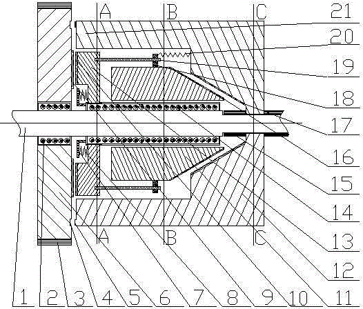
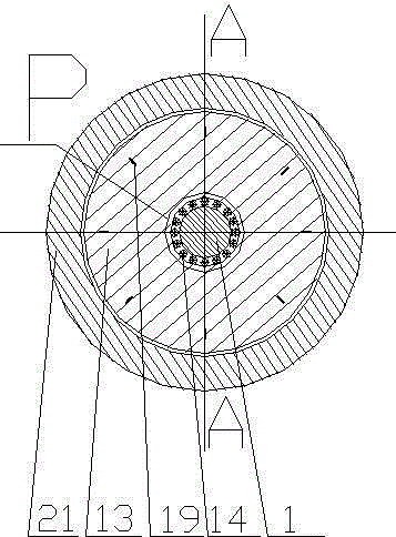
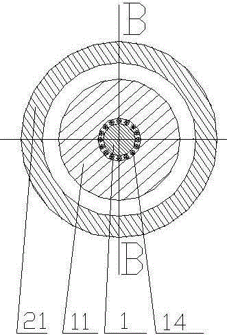
[0021] exist figure 1 In the embodiment shown in -8: the steel plate type buffering friction gear engagement clutch comprises a driving shaft 1 and a driving wheel 12 that is sleeved on the driving shaft 1, a driven wheel 6, and between the driving wheel 12 and the driven wheel A group of driven wheels between 6; it is characterized in that: the section of the driving wheel 12 is U-shaped, and the right section of the driving wheel 12, that is, the section is U-shaped, and there is a hole in the center of the bottom area, and the inner ring of the hole has a spline in the driving wheel Teeth 22, the spline teeth 22 in the drive wheel are set on the drive shaft 1, there are spline teeth 15 in the contact area between the drive shaft 1 and the spline teeth 22 in the drive wheel, and the spline teeth 15 in the drive shaft and the spline teeth in the drive wheel The key teeth 22 are matched and meshed, so that the driving wheel 12 and the driving shaft 1 always rotate at the same ...


PUM


Abstract

A steel slice type buffering friction gear engagement clutch comprises a driving shaft, a driving wheel, a driven wheel and a set of engaged wheels, wherein the driving wheel is arranged on the driving shaft in a sleeved mode, and the engaged wheels are arranged between the driving wheel and the driven wheel. The steel slice type buffering friction gear engagement clutch is characterized in that an inner spline tooth of the driving wheel is arranged on a spline tooth of the driving shaft in a sleeved mode, the length of the area of the spline tooth of the driving shaft is larger than that of the inner spline tooth of the driving wheel, the left end face of a driving wheel bucket at the left end of the driving wheel is provided with a left end face side tooth, and the driving wheel is internally provided with a driving wheel left friction inner conical face; the driven wheel is connected with the driving shaft through a driven wheel inner bearing, the right side face of the driven wheel is provided with a circle of driven wheel right side tooth, the driven wheel right side tooth and the left end face side tooth of the driving wheel bucket are matched and meshed completely, and the right side of the driven wheel is provided with a driven wheel right side friction ring; the engaged wheel set comprises a long bearing, a left engaged wheel, a right engaged wheel, a left engaged wheel left spring and a plurality of steel slices, wherein the left engaged wheel, the right engaged wheel and the left engaged wheel left spring are installed on the long bearing, and the steel slices are symmetrically installed on the outer side of the outer circumference of the right engaged wheel.

Description

technical field [0001] The invention relates to a steel plate buffer friction gear meshing clutch, which is suitable for various mechanisms requiring clutch speed change and clutch speed regulation, such as clutch speed changers of various vehicles, gearboxes of lathes, etc., and belongs to the technical field of clutch and gear transmission. Background technique [0002] Today's automobile clutches include friction clutches, fluid couplings, and electromagnetic clutches. They all use soft contact, that is, friction, hydraulic force, or electromagnetic force, to transmit the rotational power of the engine. The power transmission efficiency of these soft contacts is relatively high. Low; the reason why the modern developed automobile industry still uses the soft contact clutch method with low power transmission efficiency is because the meshed gears are difficult to separate when the gear meshing transmission rotates at high speed, and no hard transmission that is easy to mesh...

Claims


Application Information

Patent Timeline
Patent Type & Authority Patents(China)
IPC IPC(8): F16D13/60F16D13/56
Inventor 魏伯卿
Owner 贵阳渝冠技术服务中心
Why Eureka
Try Eureka