Lid for medical implant

Active Publication Date: 2022-06-14
OSTOMYCURE AS
View PDF46 Cites 0 Cited by
  • Summary
  • Abstract
  • Description
  • Claims
  • Application Information

AI Technical Summary

Benefits of technology

The invention allows for a lid to be attached to an implant by rotating it. This reduces the potential for damage to the implant and makes it easier for users to attach and remove the lid. The compression means ensures a tight seal between the lid and the implant, preventing any leaks.

Problems solved by technology

The complexity of the procedure and the high potential for complications—most of them related to dysfunction of the continence nipple valve—has deterred many surgeons from adopting the operation today.
The ileopouch anal anastomosis (IPAA) is today the gold standard worldwide for these patients but, as with a CI, this operation is also risky and failures are common, mostly leading to pouch excision with loss of bowel.
Conversion of a failed IPAA to a CI would be a preferable option but, again, surgeons are reluctant to perform this complex and unreliable technique.
However, a problem with this method of mounting a lid on an implant is that it may cause forces to be exerted on the implant which can damage the tissue-implant junction.
It can also be difficult for a patient to mount a lid in this way.
A further problem is that with this sliding method of attachment, it may be difficult for the lid to seal properly, i.e. in a leak-tight way, with the implant.
However, a problem with this attachment mechanism is that it may be possible for the coupling part to become detached from the implant, unintentionally or accidentally, for example if, e.g. by leaning on an object, pressure is applied to the coupling part causing it to be squeezed into its stressed configuration whereby it may become detached from the implant.
The closure device of WO 2011 / 039517 A1 is also relatively wide and, when attached to an implant, extends down close to the patient's skin such that there is a risk of abrasion and irritation.
Attaching the closure part to the coupling part requires two hands, which may be problematic for a user.
Also, as the closure device comprises two separate parts (the coupling part and the closure part) there is greater chance of one part becoming lost or dropped, compared with a closure device made of a single part.
Handling may also be more inconvenient.
Furthermore, there is a possibility with this closure device that it could become attached to the implant (locked) in an incorrect position, such that it is not properly seated and sealed on the implant.
For example, often a user cannot see the lid-implant interface (e.g. due to clothing or stomach being in the way) and so they may attach or lock the closure device onto the implant in an incorrect position.

Method used


Image

  • Lid for medical implant
  • Lid for medical implant
  • Lid for medical implant

Examples


Embodiment Construction

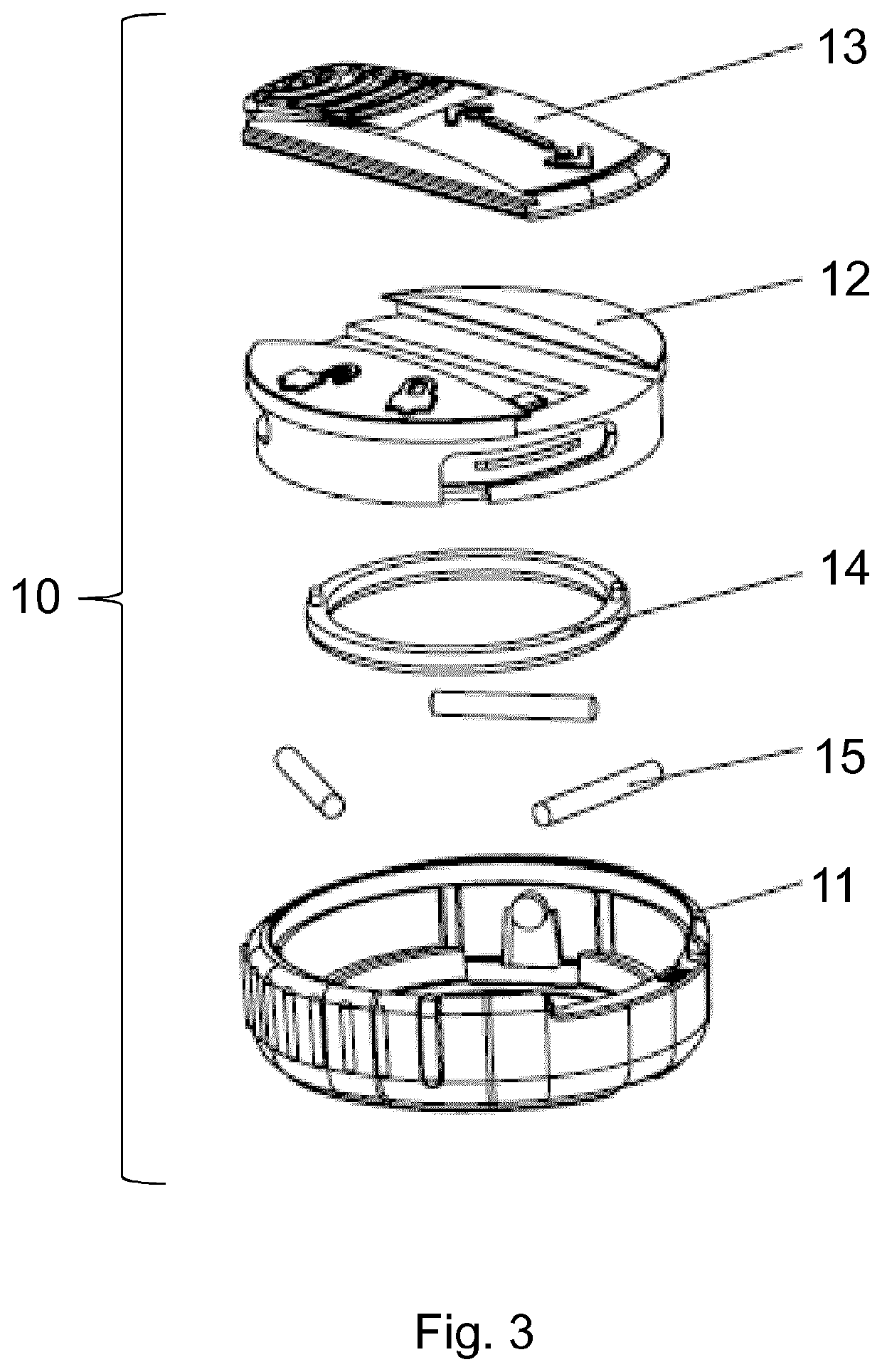
[0200]FIG. 3 shows an exploded perspective view of the components of a lid 10 according to an embodiment of the invention.

[0201]The components of the lid 10 consist of: a substantially ring-shaped base 11, a substantially circular cap 12, a slider 13, a sealing ring 14 and three pins 15. The respective components 11, 12, 13, 14, 15, of the lid 10 are described in more detail below.

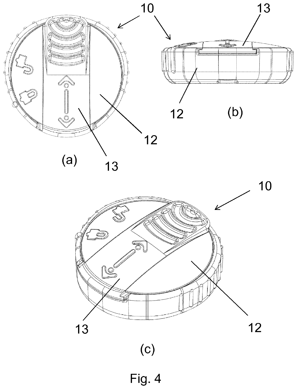
[0202]FIGS. 4(a)-(c) show top, side and perspective views, respectively, of the lid 10 of FIG. 3.

[0203]FIGS. 5(a)-(h) show a perspective, bottom, side, cross-sectional, top, side, cross-sectional and a further cross-sectional view, respectively, of the cap 12 of the lid 10 shown in FIG. 3.

[0204]The cap 12 is circular and is formed of a circular top part 28 and a ring-shaped side part 29.

[0205]In the top part 28 there is a first groove 20 which runs from one side of the top part 28, across the centre of the top part 28, to the opposite side of the top part 28. The upper surface 28a of the top part 28 slight...


PUM


Abstract

A lid for a medical implant that has first and second parts and a mechanism for engaging the implant. The second part is rotatable relative to the first part such that, in use, rotation of the second part relative to the first part causes the engaging mechanism to engage with and attach the lid to the implant.

Description

[0001]This application is a 371 filing of International Patent Application PCT / EP2017 / 064695 filed Jun. 15, 2017, which claims the benefit of British application no. 1610527.2 filed Jun. 16, 2016.BACKGROUND[0002]The present invention relates to a lid or closure device. In particular, it relates to a lid or closure device for a medical implant, more particularly for an ostomy implant.[0003]Ileostomy and colostomy are common operations which may be necessitated, for example, by malignancy or chronic bowel inflammation. The surgery is called an ileostomy if the colon and rectum are removed and a colostomy if the rectum alone is removed. Similarly an abdominal urostomy is created when the urinary bladder has to be removed due to, for example, bladder cancer. In these operations, a stoma is formed in the abdominal wall to which a bowel segment is connected.[0004]Ostomy is a generic term for any such procedure where a stoma is created.[0005]The stoma, in most cases, has to be connected to...

Claims


Application Information

Patent Timeline
IPC IPC(8): A61F5/445A61F5/44
CPCA61F5/445A61F5/4407A61F2005/4455A61F2005/4486A61F2005/4483
Inventor CARDELL, MATS ERIK KINDAHLELWING, ERIKGIDÖ SCHÖN, JIMMY CARL HENRIK
Owner OSTOMYCURE AS
Why Eureka
Try Eureka