Double-jaw plate cushioning friction thread sleeve clutch

A threaded sleeve and clutch technology, applied in clutches, magnetic drive clutches, non-mechanical drive clutches, etc., can solve the problems of difficult separation of meshed gears and low power transmission efficiency

Active Publication Date: 2016-07-13
贵阳渝冠技术服务中心
View PDF6 Cites 0 Cited by
  • Summary
  • Abstract
  • Description
  • Claims
  • Application Information

AI Technical Summary

Problems solved by technology

[0002] Today's automobile clutches include friction clutches, hydraulic couplings, and electromagnetic clutches. They all use soft contact, that is, friction, hydraulic force, or electromagnetic force, to transmit the rotational power of the engine. The power transmission efficiency of these soft contacts is relatively high. Low; the reason why the modern and developed automobile industry still uses the soft contact clutch method with low power transmission efficiency is because the meshed gears are difficult to separate when the gear meshing transmission rotates at high speed, and no hard transmission that is easy to mesh has not been found yet. The gear separation and gear meshing transmission method with higher transmission efficiency is a difficult problem in improving the transmission efficiency of automobiles; Wei Boqing's invention patent "201410151795.6 Threaded Sleeve Clutch" provides a solution, but for the driven wheel of the power output wheel When the rotation speed is greater than the rotation speed of the driving wheel, it has its shortcomings, and the solution provided by the present invention solves this deficiency

Method used


Image

  • Double-jaw plate cushioning friction thread sleeve clutch
  • Double-jaw plate cushioning friction thread sleeve clutch
  • Double-jaw plate cushioning friction thread sleeve clutch

Examples


Embodiment Construction

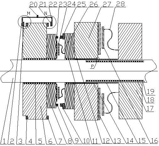
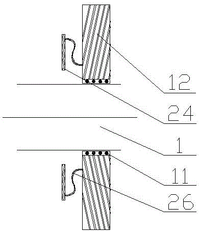
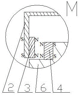
[0020] exist figure 1 In the embodiment shown in —5: the double-jaw disc buffer friction thread sleeve clutch includes a group of driving wheels and a group of driven wheels adjacent to the driving wheel 6 and a group of driven wheels adjacent to the driven wheel 27 group, the driving wheel group includes driving wheel 6 and driving wheel auxiliary wheel 8, the driven wheel group includes driven wheel 27 and driven wheel auxiliary wheel 12, driven wheel claw plate, and the driven wheel group includes driven wheel 17 and driven wheel shaft sleeve 19, passive wheel Wheel claw plate, driving wheel 6, driving wheel secondary wheel 8, driven wheel 27, driven wheel secondary wheel 12, driven wheel 17, driven wheel shaft sleeve 19, driven wheel claw plate, passive wheel claw plate are all set on the same fixed shaft 1, and is coaxial with the fixed shaft 1; it is characterized in that:

[0021] 1. There is a driven wheel claw plate between the driving wheel 6 and the driven wheel 27...


PUM


Abstract

Provided is a double-claw-disk buffer friction thread sleeve connection clutch. The double-claw-disk buffer friction thread sleeve connection clutch comprises a driving wheel set, an engaged wheel set adjacent to a driving wheel, and a driven wheel set adjacent to an engaged wheel. The driving wheel set comprises the driving wheel and a driving wheel auxiliary wheel. The engaged wheel set comprises the engaged wheel, an engaged wheel auxiliary wheel and an engaged wheel claw disk. The driven wheel set comprises a driven wheel, a driven wheel rotating shaft sleeve and a driven wheel claw disk. The same fixing shaft is sleeved with the driving wheel, the driving wheel auxiliary wheel, the engaged wheel, the engaged wheel auxiliary wheel, the driven wheel, the driven wheel rotating shaft sleeve, the engaged wheel claw disk and the driven wheel claw disk, and the driving wheel, the driving wheel auxiliary wheel, the engaged wheel, the engaged wheel auxiliary wheel, the driven wheel, the driven wheel rotating shaft sleeve, the engaged wheel claw disk, the driven wheel claw disk and the fixing shaft are concentric. The double-claw-disk buffer friction thread sleeve connection clutch is characterized in that the engaged wheel claw disk is arranged between the driving wheel and the engaged wheel, the driven wheel claw disk is arranged between the engaged wheel and the driven wheel, the engaged wheel serves as a buffer meshed wheel between the driving wheel and the driven wheel, engaged wheel internal threads are formed in the inner ring, close to the fixing shaft, of the engaged wheel, driven wheel rotating shaft sleeve external threads are formed outside the driven wheel rotating shaft sleeve, and the engaged wheel internal threads are matched with the driven wheel rotating shaft sleeve external threads.

Description

technical field [0001] The invention relates to a double-jaw plate buffer friction thread sleeve clutch, which is suitable for various mechanisms requiring clutch speed change and clutch speed regulation, such as clutch speed change devices of various vehicles, gearboxes of lathes, etc., and belongs to the technical field of clutch and gear transmission. Background technique [0002] Today's automobile clutches include friction clutches, fluid couplings, and electromagnetic clutches. They all use soft contact, that is, friction, hydraulic force, or electromagnetic force, to transmit the rotational power of the engine. The power transmission efficiency of these soft contacts is relatively high. Low; the reason why the modern developed automobile industry still uses the soft contact clutch method with low power transmission efficiency is because the meshed gears are difficult to separate when the gear meshing transmission rotates at high speed, and no hard transmission that is ...

Claims


Application Information

Patent Timeline
Patent Type & Authority Patents(China)
IPC IPC(8): F16D27/118
Inventor 魏伯卿
Owner 贵阳渝冠技术服务中心
Why Eureka
Try Eureka