Method for identifying heart status time phase

A technology of time phase and identification method, applied in the field of image processing, can solve the problems of complex calculation, dependence on electrocardiogram, complicated method of time phase identification of heart state, etc., achieve stable and accurate identification, and achieve simple effects

Active Publication Date: 2014-07-09
SHANGHAI UNITED IMAGING HEALTHCARE
View PDF9 Cites 2 Cited by
  • Summary
  • Abstract
  • Description
  • Claims
  • Application Information

AI Technical Summary

Problems solved by technology

[0007] What the present invention aims to solve is that the identification method of the time phase of the existing heart state is relatively complicated, the calculation is complicated and the problem of relying too much on the electrocardiogram

Method used


Image

  • Method for identifying heart status time phase
  • Method for identifying heart status time phase
  • Method for identifying heart status time phase

Examples


Embodiment Construction

[0018] In the following description, numerous specific details are set forth in order to provide a thorough understanding of the present invention. However, the present invention can be implemented in many other ways different from those described here, and those skilled in the art can make similar extensions without violating the connotation of the present invention, so the present invention is not limited by the specific implementations disclosed below.

[0019] Secondly, the present invention is described in detail by means of schematic diagrams. When describing the embodiments of the present invention in detail, for convenience of explanation, the schematic diagrams are only examples, which should not limit the protection scope of the present invention.

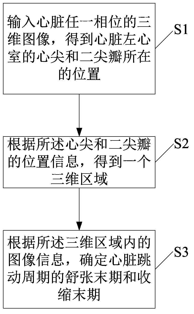
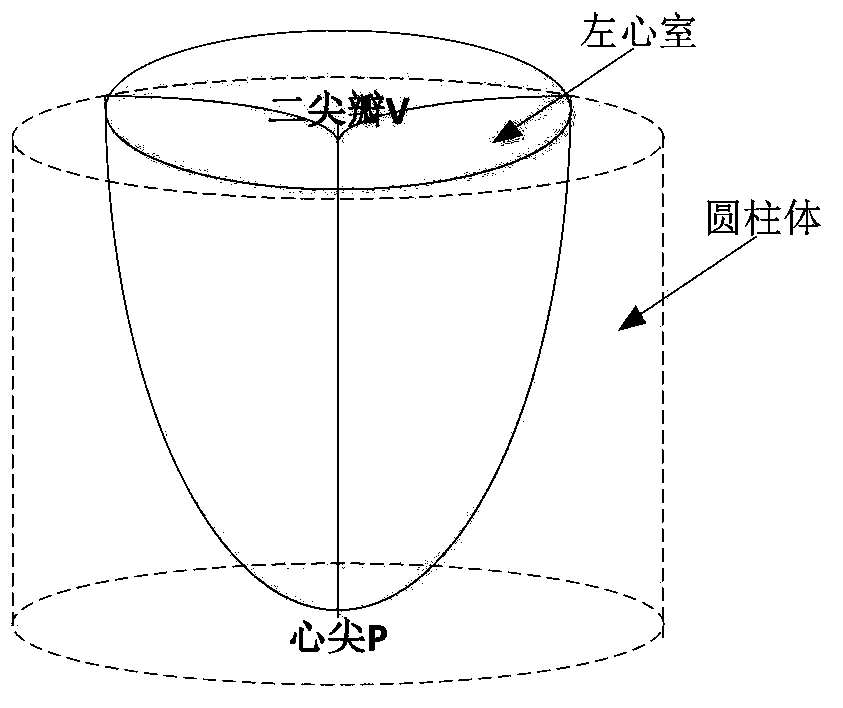
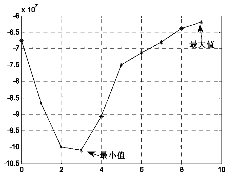
[0020] The present invention will be described in detail below in conjunction with the accompanying drawings and embodiments. The identification method of the heart state time phase of the present invention is as follows:...


PUM


Abstract

The invention discloses a method for identifying a heart status time phase. The method for identifying the time phase comprises the steps of inputting a three-dimensional heart image of any one phase to obtain the positions of the cardiac apex and the bicuspid valve of the left ventricular of the heart, obtaining a three-dimensional region according to the position information of the cardiac apex and the bicuspid valve, and determining the diastasis and the end-systole of the heartbeat cycle of the heart. The method for identifying the heart status time phase is capable of identifying the heart status time phase quickly, stably and accurately according to the gray-level distribution characteristic of the heart image, and the identification process of the method is simple and completely automatic.

Description

technical field [0001] The invention relates to the field of image processing, in particular to a method for identifying time phases of cardiac states. Background technique [0002] In the analysis of cardiac function, the usual method is to select the end-diastole (end-diastole, ED) and end-systole (end-systole, ES) of a heartbeat cycle to calculate various cardiac function indexes, such as ejection fraction, local myocardial changes, myocardial Variations in wall thickness, etc. Therefore, it is necessary to determine the images corresponding to the time phase of ED and ES in the analysis of cardiac function. [0003] At present, the methods for determining the phase of ED and ES mainly include manual observation method, ECG auxiliary judgment method, image post-processing methods such as volume judgment method and phase image gray value correlation method, etc. The manual observation method is to read the images of each phase of the heart, find the position of the left ...

Claims


Application Information

Patent Timeline
Patent Type & Authority Applications(China)
IPC IPC(8): A61B6/03A61B19/00
Inventor 黄慧庄吓海李强
Owner SHANGHAI UNITED IMAGING HEALTHCARE
Why Eureka
Try Eureka