
Ventilation device for case, case and method for ventilating

A ventilation device and chassis technology, applied in the electrical field, can solve problems such as high cost, easy installation confusion, incompatibility with PCIE chip heat dissipation requirements, etc., to achieve the effect of convenient installation and improved safety

Active Publication Date: 2017-07-07
XFUSION DIGITAL TECH CO LTD
View PDF13 Cites 0 Cited by
  • Summary
  • Abstract
  • Description
  • Claims
  • Application Information

AI Technical Summary

Problems solved by technology

[0003] However, since there are many types of PICE chips, including low-power 25W standard cards and 300W high-power GPU cards, the windshield needs to set different vents according to the configured PCIE chips, and a single type The windshield is no longer compatible with the heat dissipation requirements of all PCIE chips
[0004] The disadvantage of the prior art is that the windshield needs to be installed according to the set PCIE chip, different power PCIE chips need different windshields, and when manufacturing the windshield, multiple sets of molds are required, and the cost is too high
And there are many kinds of windshields in the same system, which are easy to be confused during installation and affect the production efficiency of the chassis

Method used


Image

  • Ventilation device for case, case and method for ventilating
  • Ventilation device for case, case and method for ventilating
  • Ventilation device for case, case and method for ventilating

Examples


Embodiment 1

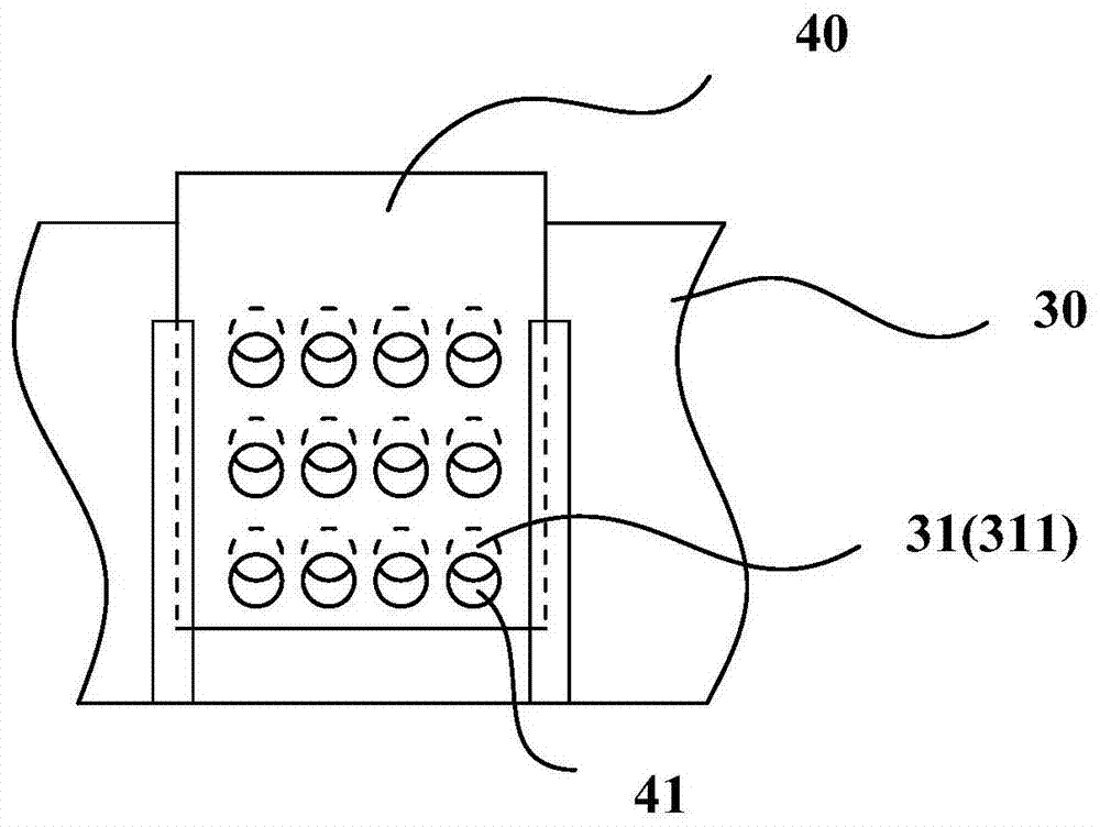
[0068] like image 3 As shown, the air vent 31 of the door baffle 40 includes a plurality of ventilation holes 311; the door baffle 40 is provided with a through hole 41 matched with each ventilation hole 311, and when the door baffle 40 moves, the air hole 311 is increased or decreased. The overlapping area of ​​the through hole 41 and the corresponding ventilation hole 311 .

[0069] Concretely, the number of the door blocking plate 40 is one, and the door blocking plate 40 is provided with a through hole 41 corresponding to each ventilation hole 311; The size is the same, when the door baffle 40 is required to open the set range, the overlapping area of ​​the through hole 41 and the ventilation hole 311 increases, thereby increasing the ventilation rate, when the door baffle 40 is required to close the set range, the through hole 41 and the ventilation hole The overlapping area of ​​311 is reduced, reducing the ventilation volume. Preferably, when the door baffle plate 40...

Embodiment 2

[0071] like Figure 4 As shown, the air vent 31 includes a plurality of air holes 311; when the door baffle 40 moves, the number of exposed air holes 311 increases or decreases.

[0072] Concretely, the number of the door blocking plate 40 is one, and the door blocking plate 40 blocks a plurality of ventilation holes 311. Figure 4 The direction shown is a reference direction, the door baffle 40 moves upwards, and the number of ventilation holes 311 exposed below increases, thereby increasing the ventilation rate. The number of 311 exposed, thereby reducing the amount of ventilation. It should be understood that the moving direction of the above-mentioned door blocking plate 40 is not limited to Figure 4 The moving manner shown can also adopt different directions such as downward, leftward, and rightward, and the moving manner is not limited.

Embodiment 3

[0074] The ventilation opening 31 includes at least one ventilation hole 311 ; there is at least one door baffle plate 40 , and each door baffle plate 40 corresponds to the setting position of each ventilation hole 311 one by one.

[0075] Specifically, the number of ventilation holes 311 is multiple, the number of door baffle plates 40 is multiple, and one door baffle plate 40 corresponds to one ventilation hole 311. Specifically, when the door baffle plate 40 needs to be opened to a set range, the Figure 5 The direction shown is the reference direction, the door baffle 40 moves upwards, and part of the ventilation holes 311 are exposed below, thereby increasing the ventilation volume. Thereby reducing the amount of ventilation. It should be understood that the moving direction of the above-mentioned door blocking plate 40 is not limited to Figure 5 In the shown moving manner, sliding in different directions such as downward, left, and right can also be used, and the slidi...


PUM


Abstract

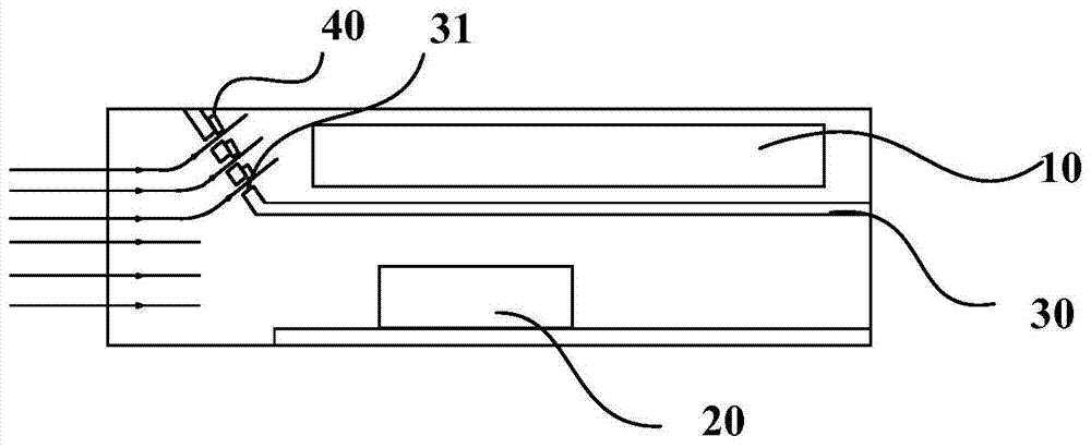
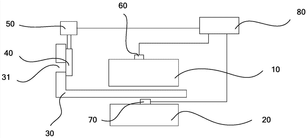
The invention relates to the field of the electrical technology, and discloses a ventilation device of a case, the case and a ventilation method. The ventilation device comprises a wind board, a fan and a door baffle, wherein the wind board is arranged in the case and divides the case into at least two spaces, a first device is arranged in the first space, a second device is arranged in the second space, and the wind board is provided with a ventilation opening; the fan supplies wind to the first space and the second space and wind blown by the fan enters the second space through the ventilation opening; the door baffle is matched with the ventilation opening and used for adjusting the size of the ventilation opening. According to the technical scheme, the door baffle is matched with the ventilation opening so that the ventilation quantity of the first device and the ventilation quantity of the second device can be adjusted, and therefore the ventilation device can be applicable to ventilation of different devices; installation of the case is facilitated, security of the devices in use is improved, and meanwhile security of the case in use is improved.

Description

technical field [0001] The invention relates to the field of electrical technology, in particular to a ventilation device for a cabinet, a cabinet and a ventilation method. Background technique [0002] In general chassis systems, in order to meet the heat dissipation requirements of key components such as CPU chips and PCIE chips, it is necessary to add structures such as air guides and windshields to realize flow distribution on demand and improve the heat dissipation efficiency of air volume. The windshield in the prior art is arranged in the chassis, and is located between the CPU chip and the PCIE chip, and the CPU chip and the PCIE chip are separated, and the windshield is provided with a vent, and the wind blown in is blown through the windshield. Sent to CPU chip and PCIE chip to cool down respectively. [0003] However, since there are many types of PICE chips, including low-power 25W standard cards and 300W high-power GPU cards, the windshield needs to be set with...

Claims


Application Information

Patent Timeline
Patent Type & Authority Patents(China)
IPC IPC(8): H05K7/20
Inventor 聂飞林俊李志新
Owner XFUSION DIGITAL TECH CO LTD
Learn More