
Ablation needle puncture path planning method and system

A path planning and ablation needle technology, applied in the medical field, can solve problems such as time-consuming, labor-intensive, interference, etc., and achieve the effect of good preoperative planning and guidance

Inactive Publication Date: 2017-05-24
GENERAL HOSPITAL OF PLA
View PDF2 Cites 3 Cited by
  • Summary
  • Abstract
  • Description
  • Claims
  • Application Information

AI Technical Summary

Problems solved by technology

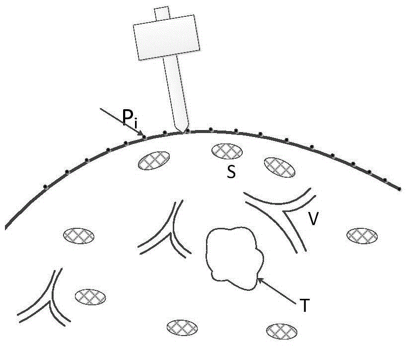
The existing ablation needle puncture path planning method is that the doctor manually plans the possible ablation needle puncture path according to the three-dimensional image of the operation area, and then the computer processes the path data to determine whether the path meets the above requirements. Highly dependent on the operator's experience, interfered by various human factors, and time-consuming

Method used


Image

  • Ablation needle puncture path planning method and system
  • Ablation needle puncture path planning method and system
  • Ablation needle puncture path planning method and system

Examples


example 1

[0069] N actual paths satisfying a given condition are offset from a reference path.

[0070] Figure 4 It is a schematic flowchart of a part of the method for planning the puncture path of the ablation needle according to the embodiment of the present invention, and the figure shows a specific example of step 4.

[0071] Step S41, selecting a reference path.

[0072] It can be selected by the operator or automatically by the method. For example, the operator can select a reference path with a better needle insertion direction based on empirical judgment based on the reference path finally obtained in step 3 . Alternatively, a reference path may be automatically selected at random, or a reference path that is virtually constrained optimal may be automatically selected.

[0073] Step S42, offsetting N actual paths from the reference path.

[0074] Offset can be done in a number of ways. For example, N actual paths can be shifted from the reference path in parallel. That i...

example 2

[0083] A group of N candidate paths satisfying the given conditions is offset from each reference path; and each group of N candidate paths is compared, and a group of N candidate paths with the highest ablation ratio or the best virtual constraint is taken as N actual path.

[0084] This example is a modification of Example 1. A group of N alternative paths that meet the given conditions are shifted from each reference path, same as Example 1.

[0085] The embodiment of the present invention also provides a puncture path planning system for an ablation needle. The system can efficiently and automatically plan the optimal puncture path of the ablation needle. Figure 6 It is a schematic structural diagram of the ablation needle puncture path planning system according to the embodiment of the present invention. like Figure 6 As shown, the ablation needle puncture path planning system includes:

[0086] An acquisition module, which acquires data of tumors, blood vessels, b...


PUM


Abstract

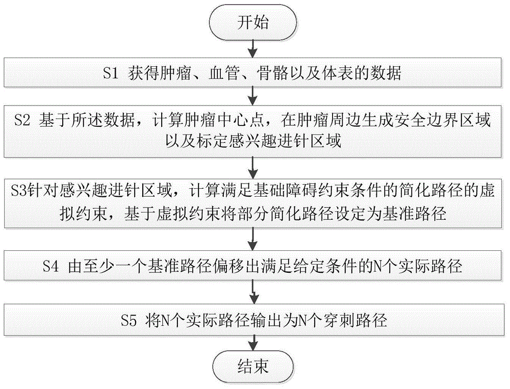
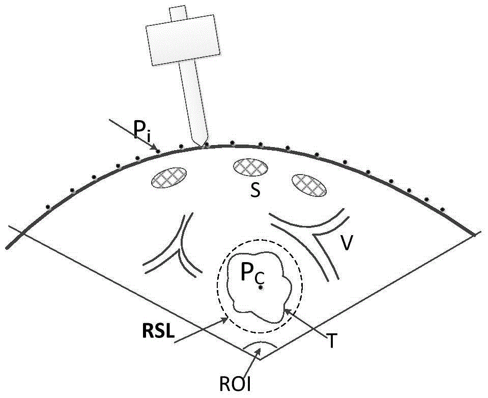
The invention discloses an ablation needle insertion path planning method which includes the steps of obtaining data of a tumor, vessels, a skeleton and a body surface; calculating the center point of the tumor on the basis of the data, generating a safety boundary area around the tumor and marking an interested needle insertion area; calculating virtual constraint of a simplified path meeting a basic disorder constraint condition according to the interested needle insertion area, and setting the simplified path to be a standard path on the basis of the virtual constraint, wherein the simplified path is a line formed by connecting a percutaneous needle insertion point to the center point of the tumor, and the basic disorder constraint condition is that the path and is not intersected with the vessels and the skeleton; forming N actual paths meeting given conditions through deviation of at least one standard path, wherein N is the number of ablation needles; outputting the N actual paths as N needle insertion paths. The invention further discloses an ablation needle insertion path planning system. By means of the method and the system, the optimal ablation needle insertion path can be efficiently and automatically planned, and good pre-operation planning guide is provided for an ablation operation.

Description

technical field [0001] The invention relates to the field of medical technology, in particular to a method and system for planning a puncture path of an ablation needle. Background technique [0002] Surgical planning for ablation therapy needs to meet various requirements, including the shortest route, avoiding vascular and bone obstacles, the number of ablation needles, the minimum trauma and the best treatment effect, etc., the virtual fixture (VF) method can solve the above problems to a certain extent Requirements, including guided virtual fixture (GVF) and obstacle virtual fixture (FRVF), GVF is used to guide the ablation needle to the desired target or move along the desired path and surface, while reducing the need for user input; the role of FRVF is Prevent the ablation needle from entering the obstacle area and avoid illegal movements such as collisions. The demand for the shortest path and the best treatment effect is the guiding type, and the vascular and bone o...

Claims


Application Information

Patent Timeline
Patent Type & Authority Patents(China)
IPC IPC(8): G06F19/00A61B34/10
Inventor 梁萍吴文波于晓玲程志刚刘方义薛劲穆梦娟
Owner GENERAL HOSPITAL OF PLA
Learn More