Respiration amplitude control mask capable of controlling tidal volume
A technology of amplitude control and tidal volume, applied in the fields of assisted puncture and medical diagnosis and treatment, it can solve the problems of increased treatment time, slow switching speed, and complicated operation, so as to relieve tension, improve comfort, and reduce leakage.
- Summary
- Abstract
- Description
- Claims
- Application Information
AI Technical Summary
Problems solved by technology
Method used
Image
Examples
Embodiment 1
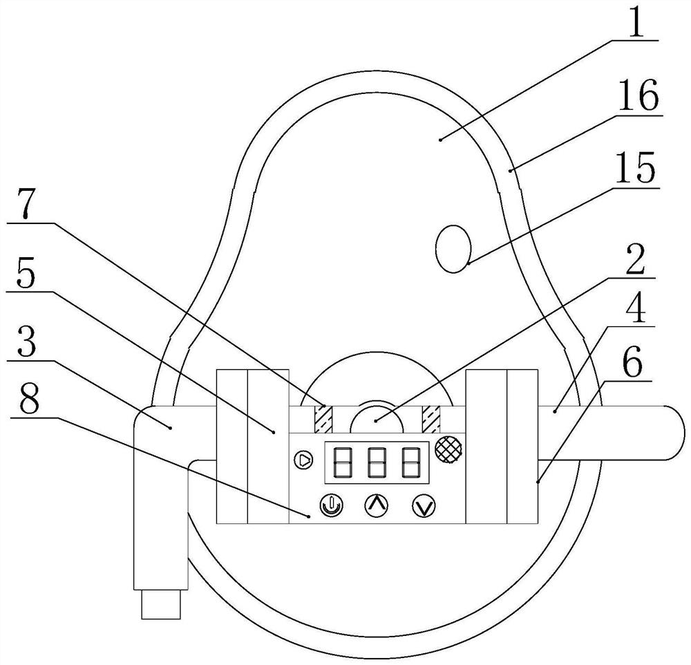
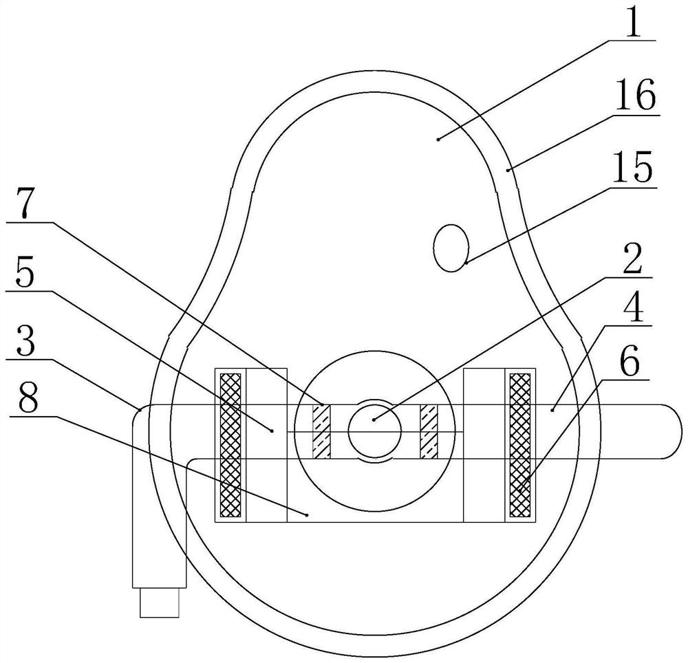
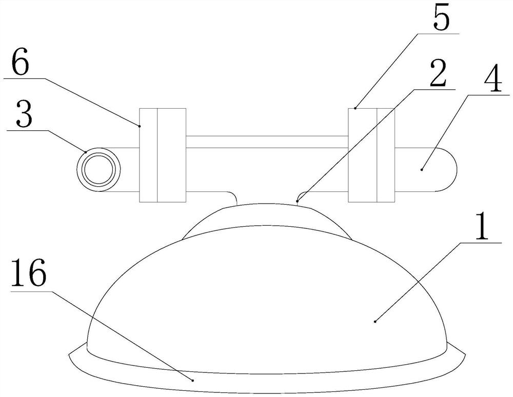
[0024] Such as Figure 1-2 As shown, a breathing range control mask with controllable tidal volume includes a fixed mask 1, a breathing pipe 2 is adhered in the middle of the fixed mask 1, and an air inlet pipe 3 and an air outlet pipe 4 are respectively fixedly connected to the two ends of the air pipe 2, so as to facilitate the separation Intake and outlet, the end of the intake pipe 3 away from the breathing pipe 2 is equipped with a solenoid valve 6, the intake pipe 3 can be closed and opened by using the solenoid valve 6, and the gas flow sensor 5 is installed at the end of the intake pipe 3 near the solenoid valve 6, which is convenient To transmit the moisture signal, the end of the gas flow sensor 5 far away from the solenoid valve 6 is attached with a flow control display 8 to facilitate the control of the solenoid valve 6 .
[0025] Existing devices are generally based on the positioning scan data, and the doctor tells the patient to take a deep breath when the first...
Embodiment 2
[0027] Example 2, see Figure 1-3 , further improvements have been made on the basis of Example 1:
[0028] In order to control the air outlet pipe 4 and prevent air leakage at one end of the air outlet pipe 4, which will affect the use of the device, a check valve 7 is installed inside the air intake pipe 3 and the end of the air outlet pipe 4 near the breathing pipe 2, and the air inlet pipe 3 can be externally connected to oxygen and an oxygen storage bag, which is convenient for the patient to inhale oxygen. The gas flow sensor 5 and the solenoid valve 6 are installed in sequence at the end of the outlet pipeline 4 close to the one-way valve 7, wherein the gas flow sensor 5 is located between the solenoid valve 6 and the one-way valve 7. The flow sensor 5 model is FS5001L, and the one-way flow of gas is controlled by the one-way valve 7, so that people inhale the gas input from the inlet pipe 3 and discharge the exhaust gas from the outlet pipe 4, and the gas flow sensor 5...
Embodiment 3
[0031] Example 3, see Figure 4 , further improvements have been made on the basis of Example 1:
[0032] In order to alarm and remind people to start inhaling or exhaling gas, a digital display 13 is installed in the middle of the flow control display 8, which is convenient to display the set number and the tidal volume of the patient at this time. The flow control display 8 is at the bottom of the digital display 13 One end is equipped with a power switch 9, which is convenient for switching on and off the flow control display 8. The end of the flow control display 8 close to the power switch 9 is equipped with an up button 11, and the end of the flow control display 8 near the up button 11 is equipped with a down button 12, which is convenient for adjusting the required moisture. The flow control display 8 is equipped with a start switch 10 near the end of the digital display 13, which is convenient for controlling the solenoid valve 6, closing and opening the inlet pipe 3 ...
PUM
 Abstract
Description
Claims
Application Information
 - R&D
- Intellectual Property
- Life Sciences
- Materials
- Tech Scout
- Unparalleled Data Quality
- Higher Quality Content
- 60% Fewer Hallucinations
Browse by: Latest US Patents, China's latest patents, Technical Efficacy Thesaurus, Application Domain, Technology Topic, Popular Technical Reports.
© 2025 PatSnap. All rights reserved.Legal|Privacy policy|Modern Slavery Act Transparency Statement|Sitemap|About US| Contact US: help@patsnap.com


