
A lcc-hvdc topology and its controllable sub-module charging initial voltage determination method
A technology of LCC-HVDC, initial charging voltage, applied in power transmission AC network and other directions, can solve problems such as threats to the normal operation of controllable sub-modules, deterioration of inverter commutation performance, and loss of self-recovery ability of inverters
Patent Information
- Authority / Receiving Office
- CN · China
- Patent Type
- Patents(China)
- Current Assignee / Owner
- Publication Date
- 2017-01-04
- Estimated Expiration
- Not applicable · inactive patent
Smart Images
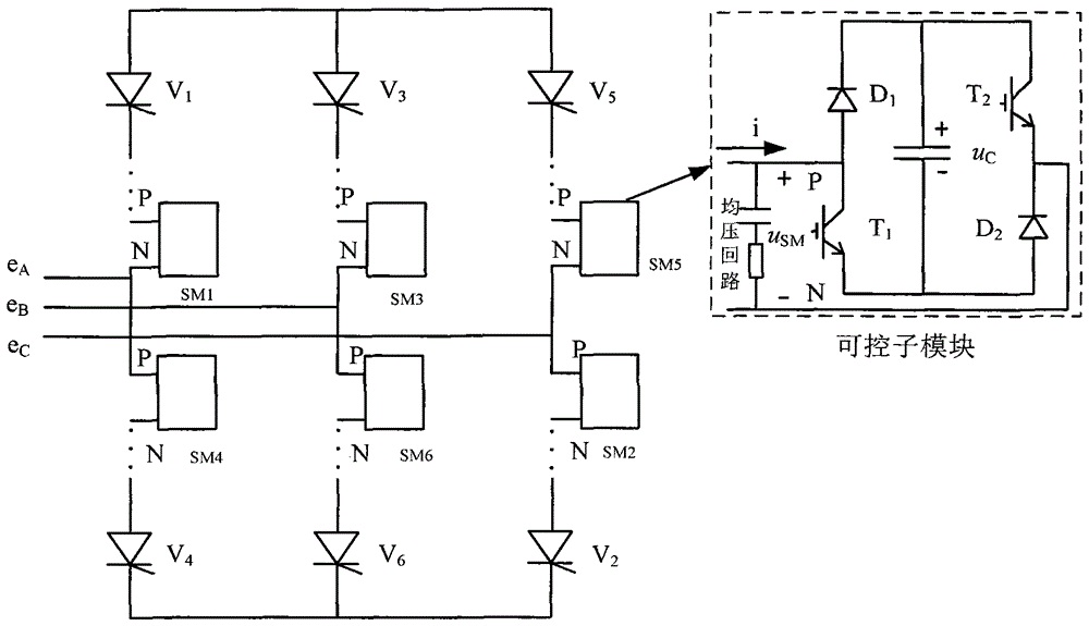
Figure 1 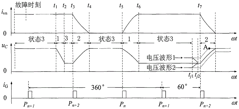
Figure 2 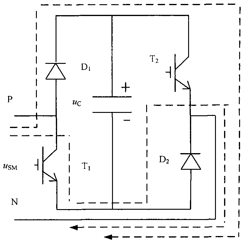
Figure 3
Abstract
Description
technical field
[0001] The invention relates to a device in the technical field of power transmission and distribution, in particular to an LCC-HVDC topology structure connected in series with controllable sub-modules and a method for determining the initial charging voltage of the controllable sub-modules. Background technique
[0002] Since the 1950s, the line-commutated-converter high-voltage direct current (LCC-HVDC) of the traditional power grid has gained rapid popularity worldwide due to its large-capacity long-distance power transmission and fast controllable active power. develop. However, since it uses a thyristor that cannot be turned off automatically as a commutation device, it needs a certain strength of the AC system to provide the commutation voltage, which has certain limitations, especially the problem of commutation failure. The occurrence of commutation failure severely limits the transmission power of the DC system, causing the transmission power to sud...
Examples
Embodiment Construction
[0048] The specific embodiments of the present invention will be further described in detail below in conjunction with the accompanying drawings.
[0049] The invention provides an LCC-HVDC topology structure with controllable sub-modules connected in series. pressure circuit. The controllable sub-module includes a capacitor and a sequentially connected device group consisting of a diode and an IGBT.
[0050] The number of the above device groups is two; the numbers of diodes and IGBTs are one respectively. The collector of the IGBT of the device group 1 of the device group is connected to the anode of the diode; the emitter of the IGBT of the device group 2 of the device group is connected to the cathode of the diode; the cathode of the diode of the device group 1 is connected to the collector of the IGBT of the device group 2 Connection; the anode of the diode of the device group 2 is connected to the emitter of the IGBT of the device group 1; the anode and the cathode of ...