Supercharge Your Innovation With Domain-Expert AI Agents!

Electronic component mounting system and substrate conveying method of electronic component mounting system

A technology for electronic component installation and substrate transportation, which is applied in the direction of electrical components, electrical components, etc., and can solve problems such as error stop, reduced operation rate, and inability to realize proper linkage of transportation actions, etc.

Active Publication Date: 2018-04-24
JUKI CORP
View PDF9 Cites 0 Cited by
  • Summary
  • Abstract
  • Description
  • Claims
  • Application Information

AI Technical Summary

Problems solved by technology

Therefore, the electronic component mounting device on the upstream side cannot complete the unloading operation of the substrate, and cannot realize proper linkage of the conveying operation, and may cause erroneous stops due to poor conveyance, etc.
As a result, the entire production line may be stopped and the operating rate may be greatly reduced.

Method used


Image

  • Electronic component mounting system and substrate conveying method of electronic component mounting system
  • Electronic component mounting system and substrate conveying method of electronic component mounting system
  • Electronic component mounting system and substrate conveying method of electronic component mounting system

Examples


Embodiment Construction

[0084] [Overall structure of the embodiment of the invention]

[0085] based on Figure 1 to Figure 14 , the embodiment of the present invention will be described.

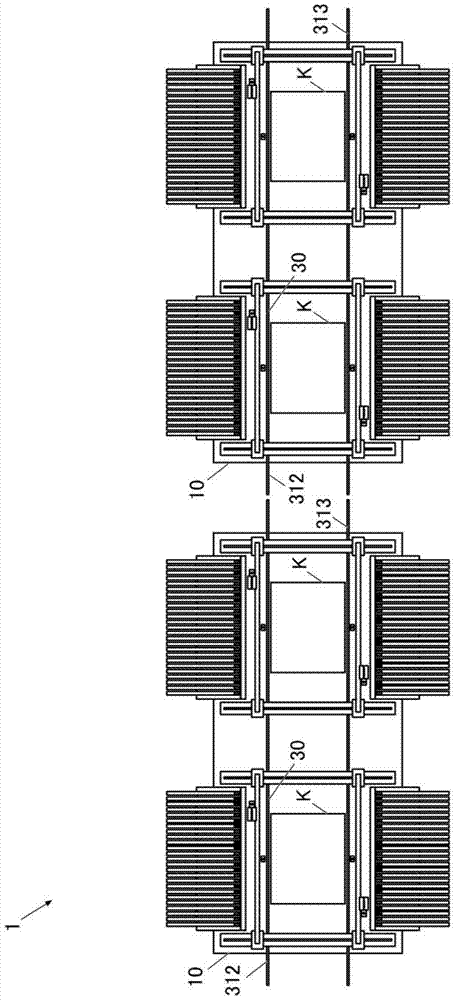
[0086] figure 1 It is a top view of the electronic component mounting system 1 which concerns on this embodiment. This electronic component mounting system 1 is constituted by two electronic component mounting apparatuses 1010 between the two electronic component mounting apparatuses 10 , 10 , and the substrate carrying-in port 313 and the substrate carrying-in port 312 of the substrate conveying device 30 are arranged close to each other and facing each other. As a result, the substrate K can be transferred between the two electronic component mounting apparatuses 10 , 10 .

[0087] In addition, the electronic component mounting system 1 is particularly characterized in the structure, control, and transfer method for transferring the substrate K between two electronic component mounting apparatuses arranged in...


PUM


Abstract

The present invention provides an electronic component mounting system and a substrate conveying method of the electronic component mounting system, which perform transfer between devices for large substrates. The electronic component mounting system (1) performs temporary stop control and restart control when transferring a large substrate (K1). During the temporary stop control, the control unit (90B) uses the downstream side sensor (378B) The substrate detection performed temporarily stops the conveyance, and the control unit (90A) temporarily stops the conveyance according to the temporary stop notification from the downstream electronic component mounting device. During restart control, if the control unit determines that the downstream electronic component When the working area of ​​the component mounting device is empty, the transportation is restarted, and the control unit of the upstream electronic component mounting device receives a notification of permission to carry into the working area from the downstream electronic component mounting device, and restarts the transportation.

Description

technical field [0001] The present invention relates to an electronic component for carrying out substrate transport between two transport mechanisms [0002] A mounting system and a substrate delivery method thereof. Background technique [0003] In a conventional electronic component mounting device, the range of a working area for mounting components on a board inside the device is determined in accordance with the external dimensions of the device, and the upper limit of the size of the board on which components can be mounted is determined accordingly. Therefore, by adjusting the position of the sensor for determining the position of the board in the work area to the downstream side in the conveyance direction, the board in the work area is further arranged downstream in the conveyance direction, and the electronic components are mounted. Mounting work of a substrate larger than a predetermined size (for example, refer to Patent Document 1). [0004] On the other hand...

Claims


Application Information

Patent Timeline
Patent Type & Authority Patents(China)
IPC IPC(8): H05K13/04
Inventor 安藤正小原诚子野尻信明麻生文彦
Owner JUKI CORP
Features
  • R&D
  • Intellectual Property
  • Life Sciences
  • Materials
  • Tech Scout
  • Unparalleled Data Quality
  • Higher Quality Content
  • 60% Fewer Hallucinations
Learn More