Retaining plate

A technology for retaining plates and traps, which is applied to suction filters, cleaning equipment, vacuum cleaners, etc., can solve the problems of expensive, complex retaining plates of plastic materials, and inability to join retaining plates, and achieve low tool cost, fast and economical production process Effect

Active Publication Date: 2014-08-20
欧罗菲利特斯公司
View PDF11 Cites 7 Cited by
  • Summary
  • Abstract
  • Description
  • Claims
  • Application Information

AI Technical Summary

Problems solved by technology

[0005] As shown above, therefore, in practice, the low-cost production of the holding plate made of cardboard has the disadvantage that it cannot be joined without problems with the plastic material non-woven bag. The plates have to be manufactured with corresponding tools which are very expensive, so it is very complicated to manufacture plastic material retaining plates in the injection molding method

Method used


Image

  • Retaining plate
  • Retaining plate

Examples


Embodiment Construction

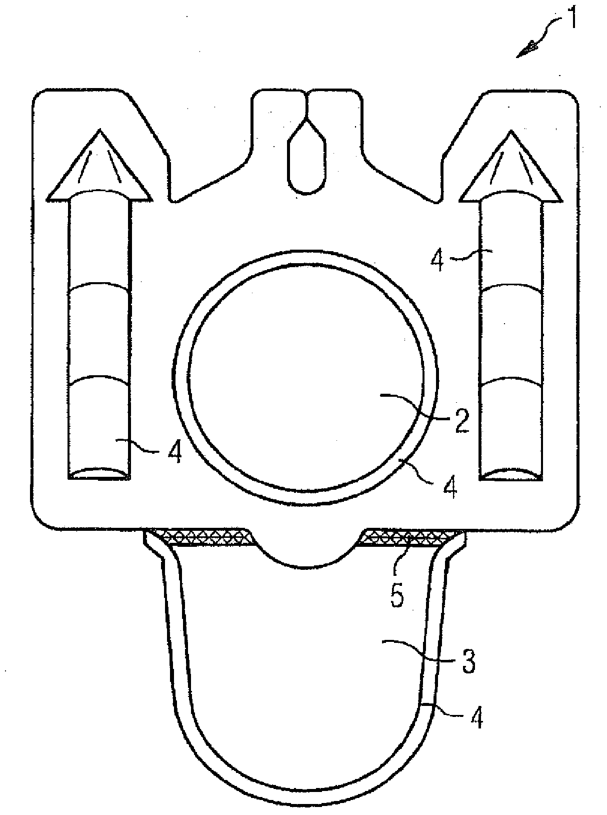
[0017] figure 1 The retaining plate 1 shown in has an inlet 2 which can be closed by a flap 3 . figure 1 The embodiment shown in is constructed as a one-piece part, ie the holding plate 1 is formed from a film by thermoforming and stamping. Such as figure 1 As described in , the retaining plate 1 also has reinforcing ribs 4 . The reinforcing rib 4 can be configured in various ways. They are preferably configured (similarly to the ribs 4 ) as arrowheads with a high-deep structure. The reinforcing ribs 4 can also be replaced by reinforcing fibers, which are present in the membrane, or which are present in combination with said reinforcing ribs. Therefore, the flap 3 is integrated with the retaining plate 1 via the film hinge 5 . Due to the fact that the flap 3 can be joined to the retaining plate 1 by means of a film hinge 5, since the flap 3 does not need to be joined to the remaining parts of the retaining plate 1 in a separate step, the flap 3 and the retaining plate 1 c...


PUM


Abstract

The invention relates to a retaining plate for a vacuum cleaner bag, which retaining plate has an inlet opening, wherein the retaining plate is formed by thermoforming and subsequent punching of a film made of a thermoplastic material.

Description

technical field [0001] The invention relates to a retaining plate for a vacuum cleaner bag having an inlet, the retaining plate being formed by thermoforming and subsequently stamping a film made of thermoplastic material. Background technique [0002] Retention sheets for vacuum cleaner filter bags are known in the art and are made of cardboard or plastic material. [0003] Cardboard retainer plates are stamped from cardboard sheets. Possibly, a rubber seal is bonded to the cardboard retaining plate. Thicker and stronger cardboard retaining boards are made by laying one layer of cardboard on top of another or folding one layer of cardboard on top of another and bonding the layers of cardboard. Therefore, it is also possible to fix the rubber seal between two layers of cardboard. It is also common to be fitted with manual seals or automatic seals with which the filter bag can be closed before it is removed from the vacuum cleaner. Solutions with slides (eg EP1284629B1 ) ...

Claims


Application Information

Patent Timeline
Patent Type & Authority Applications(China)
IPC IPC(8): A47L9/14
CPCA47L9/1436A47L9/1445
Inventor 简·舒尔廷克拉尔夫·赛耶
Owner 欧罗菲利特斯公司
Why Eureka
Try Eureka