Vacuum panel sucking and hoisting crane

A technology of suction hoist and vacuum suction cup, which is applied to cranes, load hanging elements, walking bridge cranes, etc. labor, ensuring non-destructive handling, and saving labor

Active Publication Date: 2014-09-03
江苏长诚智能装备有限公司
View PDF5 Cites 8 Cited by
  • Summary
  • Abstract
  • Description
  • Claims
  • Application Information

AI Technical Summary

Problems solved by technology

In the prior art, it is difficult for the suction hoist to meet the requirements of lifting and handling only by simple flipping action
At the same time, as more and more large-area plates are used, using the cylinder to drive the flip joint to complete the handling will lead to an increase in the failure rate and a higher risk of causing a large production accident.

Method used


Image

  • Vacuum panel sucking and hoisting crane
  • Vacuum panel sucking and hoisting crane
  • Vacuum panel sucking and hoisting crane

Examples


Embodiment 1

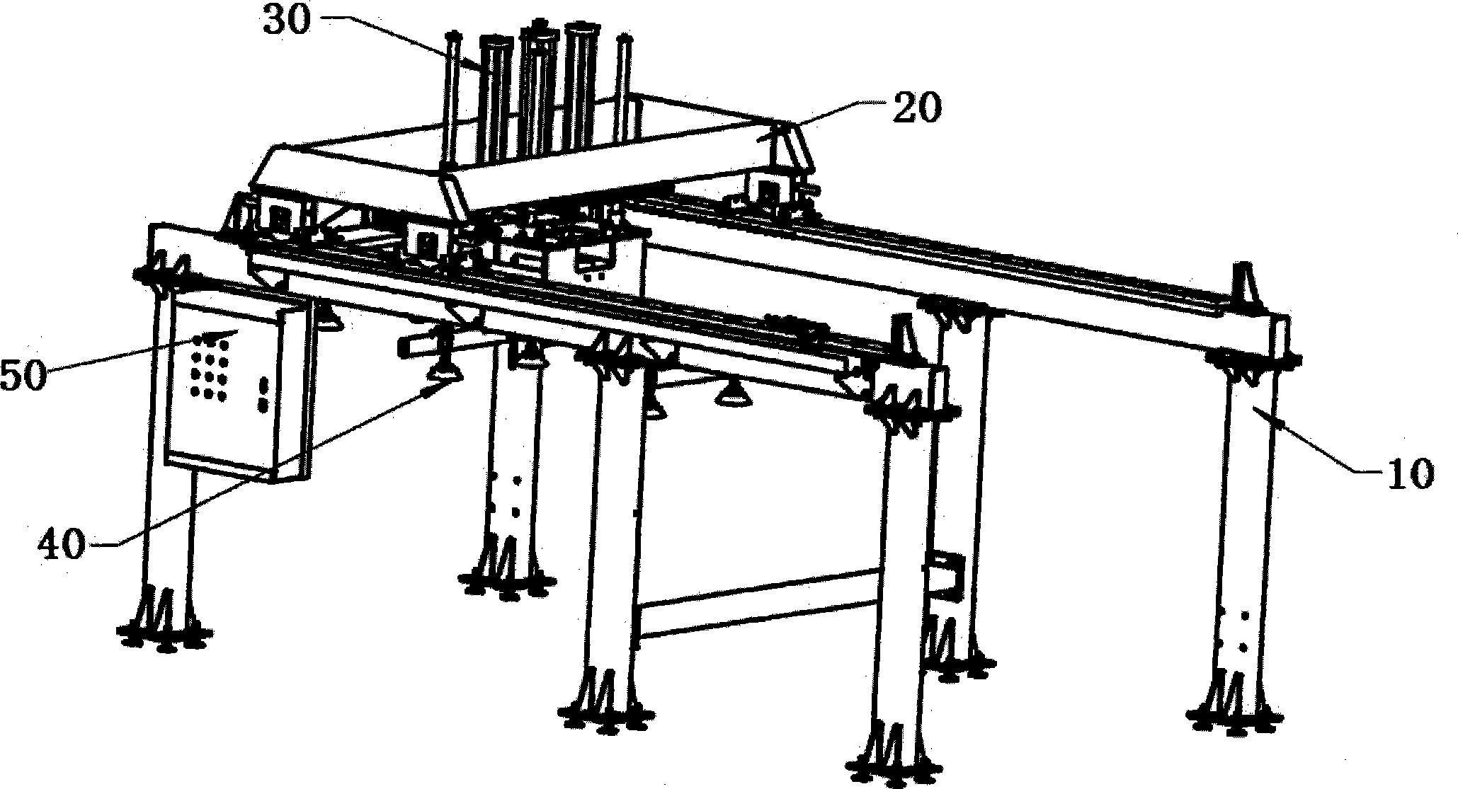
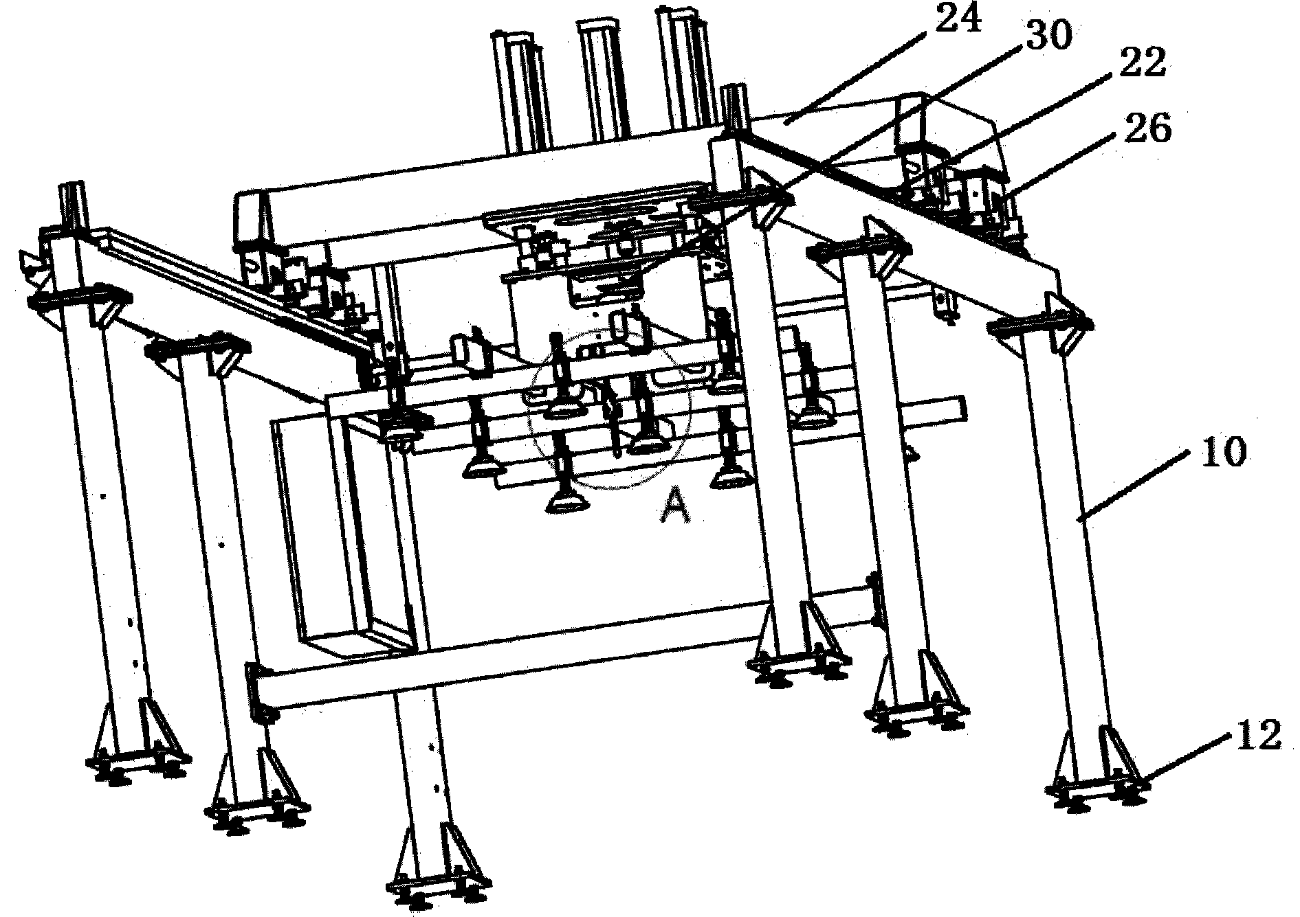
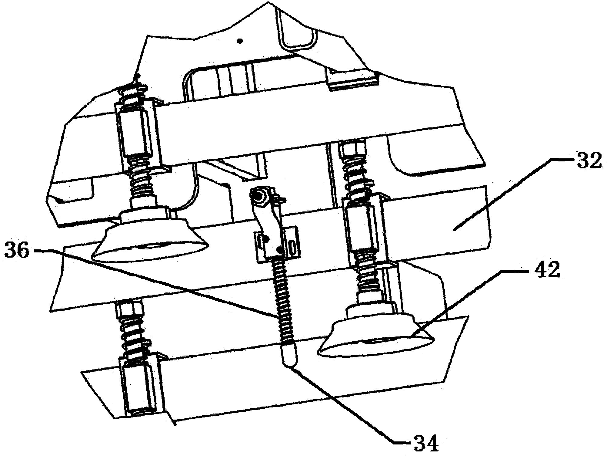
[0017] as attached Figure 1-3 As shown, the plate vacuum lifting machine described in this embodiment includes a frame 10, a traveling mechanism 20, a lifting mechanism 30, a vacuum suction cup set 40, and an electrical control device 50; the frame 10 is welded by section steel and is light in weight. , with large load and beautiful appearance, it is the basis for carrying materials and fixing the traveling device, with adjusting bolts 12 at the bottom for adjusting the level of the equipment during installation; the traveling mechanism 20 includes a linear guide rail 22 and a moving head 24, the linear The guide rail 22 is horizontally arranged on the frame 10, and the moving head 24 can move linearly back and forth on the linear guide rail through the rack and pinion 26. As an example, the rack and pinion can be driven by a reduction motor Provide power; and the lifting mechanism 30 is arranged in the moving head 24 and can move up and down relative to the moving head. The ...


PUM


Abstract

The invention relates to a vacuum panel sucking and hoisting crane. The vacuum panel sucking and hoisting crane comprises a rack, a walking mechanism, a hoisting mechanism and a vacuum chuck group, wherein the walking mechanism comprises a linear guide rail and a movable machine head, the linear guide rail is horizontally arranged on the rack, the movable machine head is capable of linearly reciprocating on the linear guide rail through a gear and a rack, the hoisting mechanism is arranged in the movable machine head and is capable of moving up and down relative to the movable machine head, a cross beam is arranged at the lower part of the hoisting mechanism, a panel detection sensing probe is connected to the cross beam through a detection rod, and a plurality of vacuum chucks are arranged on the cross beam. The vacuum panel sucking and hoisting crane provided by the invention is especially suitable for sucking and hoisting of stainless steel, and can be applied to feeding of a veneer reeling machine, thereby reducing heavy labor of manual carrying, and ensuring undamaged carrying of panels; meanwhile, through transmission of signals between upstream equipment and downstream equipment, unattended operation can be realized, and the labor is maximally saved; the vacuum sucking and hoisting crane has the characteristics of high efficiency, safety, rapidness, and labor saving.

Description

technical field [0001] The invention belongs to the technical field of hoisting devices, and more specifically, the invention relates to a board vacuum suction hoist. Background technique [0002] Vacuum lifter is a device that uses "vacuum suction" to lift and transfer heavy objects without resorting to other power, such as cranes, mechanical arms, hydraulic cylinders, etc. In the prior art, the suction hoist realizes the adsorption function through the vacuum pump, and realizes the turning function through the cylinder driving the turning joint. In the prior art, it has been difficult for the suction hoist to meet the requirements of lifting and transporting only by simple turning action. At the same time, as more and more large-area plates are used, using the cylinder to drive the flip joint to complete the handling will lead to an increase in the failure rate and a higher risk of causing a large production accident. Contents of the invention [0003] In order to solv...

Claims


Application Information

Patent Timeline
IPC IPC(8): B66C1/02B66C17/00
Inventor 韦辉明
Owner 江苏长诚智能装备有限公司
Why Eureka
Try Eureka