A device for measuring the corrosion rate of downhole pipe string by flue gas and its application

A technology of corrosion rate and downhole pipe string, which is applied in the field of devices for measuring the corrosion rate of downhole pipe string by flue gas, and can solve the problems of inaccurate simulation of downhole multi-component system components and other problems

Active Publication Date: 2016-11-30
CHINA UNIV OF PETROLEUM (EAST CHINA)
View PDF7 Cites 0 Cited by
  • Summary
  • Abstract
  • Description
  • Claims
  • Application Information

AI Technical Summary

Problems solved by technology

[0006] At present, the devices used to study corrosion by weight loss method are relatively simple, and cannot be used to simulate the corrosivity of flue gas in assisted heavy oil production by flue gas injection. % N 2 , 10%-15% CO 2 , 4%-6% O 2 , and SO 2 , SO 3 , HCl, etc., considering the dissolution of gas, under laboratory conditions, only according to Dalton's law of partial pressure, it is impossible to accurately simulate the composition of the downhole multi-component system

Method used


Image

  • A device for measuring the corrosion rate of downhole pipe string by flue gas and its application
  • A device for measuring the corrosion rate of downhole pipe string by flue gas and its application
  • A device for measuring the corrosion rate of downhole pipe string by flue gas and its application

Examples


Embodiment 1

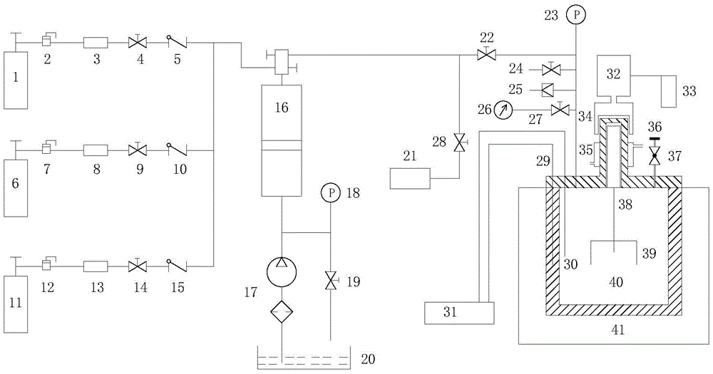
[0057] A device for measuring the corrosion rate of flue gas on downhole pipe strings, including a gas source part, a gas mixing part and a reactor 40 simulating a corrosion environment;

[0058] The gas source part includes a nitrogen gas source 1, an oxygen gas source 6, and a carbon dioxide gas source 11;

[0059] The gas mixing section includes a mixing pressurized container 16;

[0060] The reaction kettle 40 of the simulated corrosive environment comprises a kettle body, an experimental rotating part axially arranged in the kettle body, a motor 32 driving the experimental rotating part, and the experimental rotating part includes a rotor 38 and a coupon holder 39. The motor 32 includes a speed controller 33 and a magnetic transmission device 34; a rubber sealing sheet and a ball valve are arranged on the top of the kettle body; the ball valve is vertically installed on the top of the kettle body, and a rubber sealing sheet is encapsulated on the ball valve ;

[0061] T...

Embodiment 2

[0070] A device for measuring the corrosion rate of flue gas to downhole pipe strings as described in Example 1, the difference is that the pipeline between the nitrogen gas source 1 and the mixing pressurized container 16 is sequentially provided with a first decompression Valve 2, first gas mass flow meter 3 and first one-way check valve 5;

[0071] A second pressure reducing valve 7, a second gas mass flow meter 8 and a second one-way check valve 10 are arranged in sequence on the pipeline between the oxygen source 6 and the mixing pressurized container 16;

[0072] A third decompression valve 12 , a third gas mass flow meter 13 and a third one-way check valve 15 are arranged in sequence on the pipeline between the carbon dioxide gas source 11 and the mixing pressurized container 16 .

Embodiment 3

[0074] A working method of the device for measuring the corrosion rate of the downhole pipe string by flue gas as described in embodiment 1, comprising the following steps:

[0075] (1) Referring to the standard JB / T 7901. Metal material laboratory uniform corrosion full immersion test method, the downhole pipe string to be tested is processed into a sample to be tested that meets the above standards, and the sample to be tested is punched to measure the The mass M of the sample to be tested before the test; the sample to be tested is fixed on the rack;

[0076] (2) the coupon rack is installed on the rotor, and then the reaction kettle of the simulated corrosion environment is sealed;

[0077] (3) the valve on the pipeline between the mixing pressurized container and the reactor of the simulated corrosion environment, the valve on the pipeline between the vacuum gauge and the reactor of the simulated corrosion environment and the valve at the vacuum pump end are opened respec...


PUM


Abstract

The invention relates to a device for measuring the corrosion rate of flue gas on downhole pipe strings, which includes a gas source part, a gas mixing part and a reaction kettle for simulating a corrosion environment; the gas source part includes a nitrogen gas source, an oxygen gas source, and a carbon dioxide gas source The gas mixing part includes a mixing pressurized container; the reaction kettle of the simulated corrosion environment includes a kettle body, an experimental rotating part axially arranged in the kettle body, a motor driving the experimental rotating part, and the experimental rotating part includes Rotor and rack. The invention can simulate the real condition of downhole pipe string corrosion in flue gas injection assisted heavy oil exploitation, and satisfies the test of flue gas corrosivity under different conditions.

Description

technical field [0001] The invention relates to a device for measuring the corrosion rate of flue gas to downhole pipe strings and its application, belonging to the technical field of oil and gas field development. technical background [0002] Flue gas injection-assisted heavy oil recovery is an effective measure to increase crude oil production and ultimate recovery. Heavy oil occupies a relatively large proportion of the world's oil and gas resources. At present, the main methods of mining heavy oil are steam flooding, steam huff and puff, SAGD, etc. In the existing steam flooding process, the flue gas of the steam injection boiler is directly discharged into the atmosphere, but In fact the flue gas can be used for oil displacement. When flue gas injection assists heavy oil recovery, because the flue gas contains CO 2 , O 2 , SO 2 Injection wells and production wells will be corroded to varying degrees, and even downhole casings will be corroded and perforated, result...

Claims


Application Information

Patent Timeline
Patent Type & Authority Patents(China)
IPC IPC(8): G01N17/00
Inventor 杨肖曦秦国顺李松岩麻涛李威郭龙江
Owner CHINA UNIV OF PETROLEUM (EAST CHINA)
Why Eureka
Try Eureka