surgical anastomosis device

A technique of surgery and components, applied in the direction of surgical fixation nails, etc.

Active Publication Date: 2018-02-13
TYCO HEALTHCARE GRP LP
View PDF10 Cites 0 Cited by
  • Summary
  • Abstract
  • Description
  • Claims
  • Application Information

AI Technical Summary

Problems solved by technology

[0005] Although the reloader configuration described above provides many advantages, it may be desirable to prevent inadvertent firing of the knife of a surgical stapler when the staple cartridge is not installed or spent

Method used


Image

  • surgical anastomosis device
  • surgical anastomosis device
  • surgical anastomosis device

Examples


Embodiment Construction

[0186] Detailed embodiments of the present disclosure are disclosed here, however, the disclosed embodiments are merely examples of the present disclosure, and the present disclosure can be embodied in various forms. Therefore, specific structural and functional details disclosed herein are not to be interpreted as limiting, but merely as a basis for the claims and as a means for teaching one skilled in the art to construct various structures in substantially any suitably detailed structure. manner using the representative basis of this disclosure.

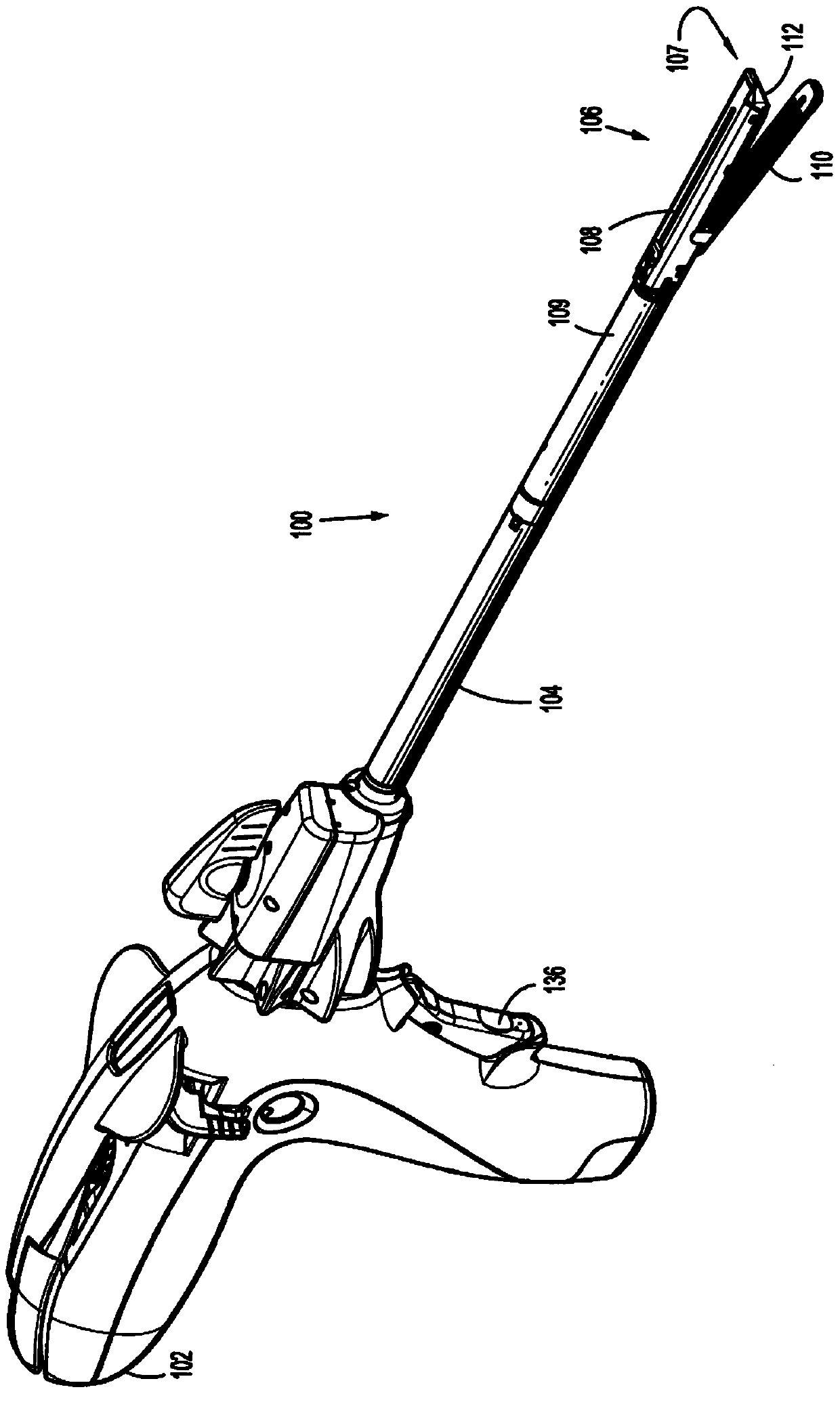
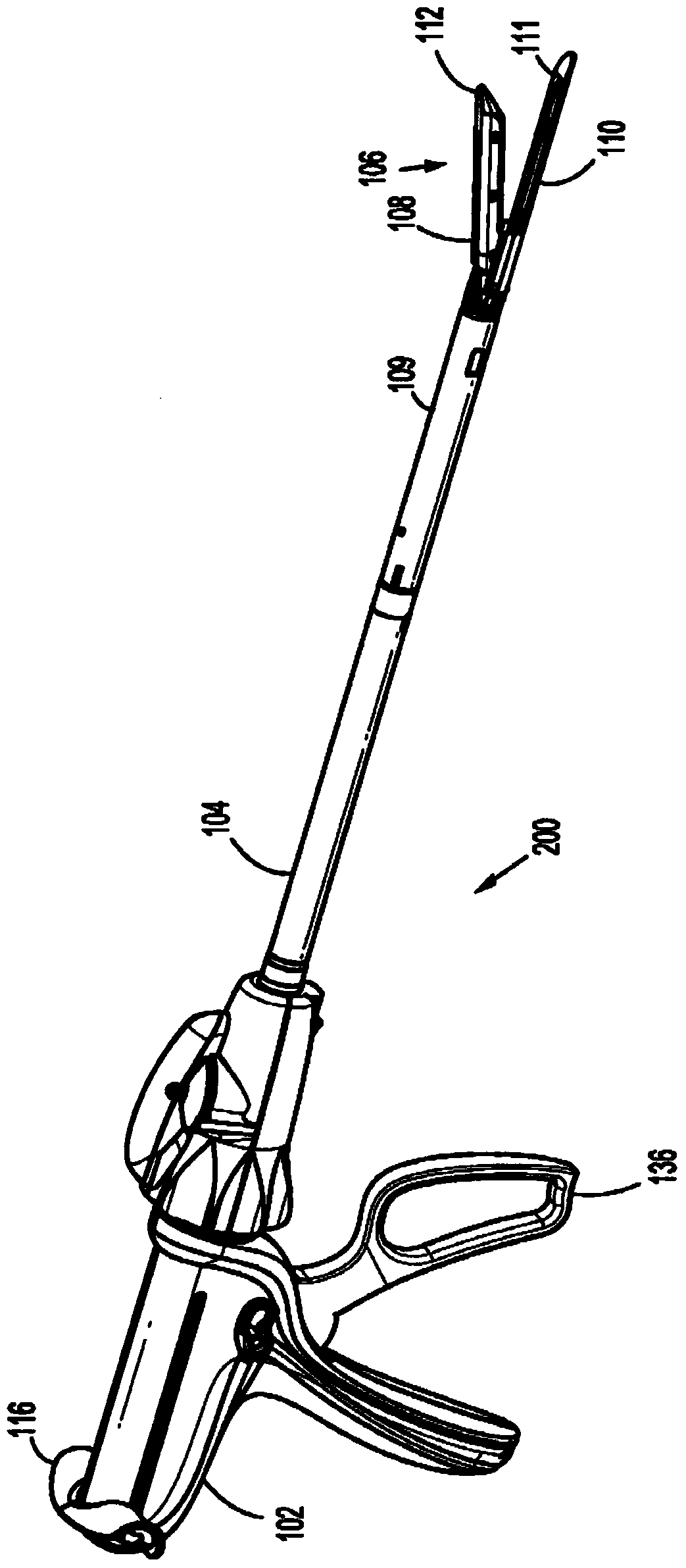
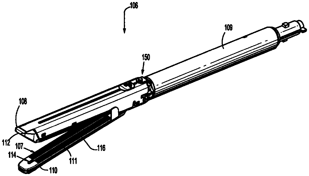
[0187] In accordance with the present disclosure, various drive lock mechanisms are disclosed herein and configured for use with a reload adapted to connect to one or more surgical stapling devices. Various drive lock mechanisms are configured to prevent false firing of the knife if no staple cartridge is installed, or to prevent firing if an empty staple cartridge is installed.

[0188] figure 1 A powered surgical stapling devi...


PUM


Abstract

The present invention provides a surgical stapling device (stapler). The stapler includes a housing, an elongated member, and a reloader. The staple cartridge is configured to be selectively connected to the first jaw member of the reloader and includes one or more resilient members on the staple cartridge. An anvil operatively supported on the second jaw member of the reloader is configured to compress one or more fasteners ejected from the staple cartridge. The anvil includes one or more locking members thereon. The cutter is configured to translate through the staple cartridge and anvil when the first and second jaw members are in a closed configuration. Engagement between the cutter and the resilient member causes the resilient member to move from an initial configuration that allows the cutter to move distally past the locking member to a final configuration that allows the locking member to engage the cutter.

Description

[0001] Cross References to Related Applications [0002] This application claims the benefit of and priority to US Provisional Patent Application No. 61 / 779,873, filed March 13, 2013, which is hereby incorporated by reference in its entirety. technical field [0003] The present disclosure relates to a surgical stapling device. More specifically, the present disclosure relates to surgical stapling devices including knife actuated locking mechanisms. Background technique [0004] Surgical stapling devices configured to staple and subsequently sever tissue are well known in the art. Such stapling devices typically include a housing and an elongated member extending from the housing. In some examples, a multi-use loading unit (MULU) including a reload may be configured to releasably engage the distal end of the elongate member. Optionally, the reload may be fixedly supported at the distal end of the elongate member. In any of the reload configurations described above, the a...

Claims


Application Information

Patent Timeline
Patent Type & Authority Patents(China)
IPC IPC(8): A61B17/072
CPCA61B17/068A61B17/07207A61B2017/07271A61B2090/08021A61B2017/07278A61B2017/07257
Inventor 贾斯汀·威廉斯克里斯托弗·彭纳李 安·奥尔森斯坦尼斯瓦夫·马尔奇克肯尼斯·M·卡波拉托马斯·R·赫斯勒欧内斯特·奥拉尼斯坦尼斯洛娃·科斯切夫斯基
Owner TYCO HEALTHCARE GRP LP
Why Eureka
Try Eureka