Medical anastomat detection device

A detection device and stapler technology, applied in the field of medical equipment production, can solve problems such as radiation leakage, omission or judgment error, tearing, etc., and achieve high efficiency and reliable detection

Pending Publication Date: 2020-01-14
NANJING VOCATIONAL UNIV OF IND TECH
View PDF0 Cites 7 Cited by
  • Summary
  • Abstract
  • Description
  • Claims
  • Application Information

AI Technical Summary

Problems solved by technology

If there is a lack of staples in the finished stapler, it will cause uneven anastomosis tension on both sides of the wound, tear the surface tissue of the wound and cause anastomosis failure, which will bring pain and even enlargement of the second wound suture to the patient Pain, which increases the risk of surgical failure, so the finished stapler must ensure that the staples are embedded in the mold base without any defects, which requires strict quality inspection of the stapler during production
Because the staples are very small and dense

Method used


Image

  • Medical anastomat detection device
  • Medical anastomat detection device
  • Medical anastomat detection device

Examples


Embodiment 1

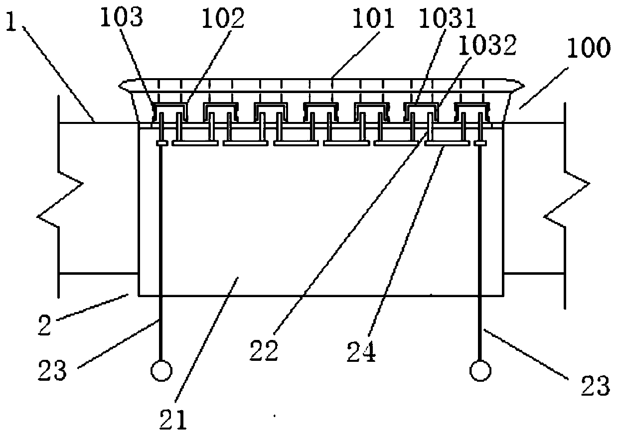
[0038] like image 3 As shown, the stapler 100 includes a mold base 101 and staples 103. Several rows of nail grooves 102 are arranged in the mold base 101. Each row of nail grooves 102 includes a plurality of nail grooves arranged at equal intervals. Each nail groove 102 contains Staples 103 can be provided, and each staple 103 includes a nail body 1031 and two nail feet 1032 located at two ends of the nail body 1031 .

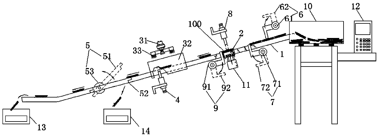
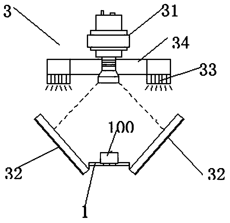
[0039] refer to Figure 1-8 , a staple detection device provided by an embodiment of the present invention is used to detect a stapler, including a conveying guide rail 1, an electrical measuring contact 2, an electrical measuring contact moving mechanism, a photographing device 3, and a first mold base blocking mechanism , The second mold base blocking mechanism, the third mold base blocking mechanism, the turnover plate mechanism 5, the feeding vibration plate 10 and the computer 12.

[0040] refer to figure 1 , the bottom of the transport rail 1 is fixe...

Embodiment 2

[0056] Basically the same as the embodiment, the difference is:

[0057] The electric measuring contact 2 comprises a contact seat 21, and the top of the contact seat 21 is fixedly provided with several pairs of electrodes 22 corresponding to each nail groove 102 in the mold base 101, and the bottoms of the electrodes 22 are all fixed in the contact seat 21, The top all protrudes from the contact base 21, and the number of pairs of electrodes 22 is consistent with the number of nail grooves 102 on the mold base 101, and the two electrodes in each pair of electrodes 22 are facing to the two opposite inner walls of the corresponding nail groove 102 respectively. The arc-shaped contact tongues 221 are respectively extended so that if the staples 103 are correctly embedded in the nail grooves 102, the distance between the two contact tongues 221 in each pair of electrodes 22 is equal to the two distances between the staples 103 in the nail grooves 102. The distance between the nai...


PUM


Abstract

The invention discloses a medical anastomat detection device. The medical anastomat detection device comprises a conveying guide rail, an electric measuring contact, an electric measuring contact moving mechanism, a shooting device, a third die holder blocking mechanism and a turnover plate mechanism, wherein the electric measuring contact comprises a contact pedestal, a plurality of pairs of electrodes corresponding to nail grooves in an anastomat die holder are fixedly arranged at the top of the contact pedestal, the bottoms of the electrodes are all fixed in the contact pedestal, and the tops of the electrodes extend out of the contact pedestal. According to the medical anastomat detection device, by arranging the electric measuring contact, the electric measuring contact is matched with anastomosis nails in an anastomat to form an equivalent capacitance circuit or a switch circuit, the embedding integrity of the anastomosis nails in the anastomat can be detected by measuring the equivalent capacitance value or the state of the switch circuit, the detection is reliable, and the efficiency is high.

Description

technical field [0001] The invention relates to the field of medical equipment production, in particular to a detection device for a medical stapler. Background technique [0002] In the medical and clinical field, a stapler is a device used for suturing wound epidermis and coelenteric incision. The device is mainly composed of a mold base and staples. In the application of clinical operations, the staples are pushed out from the mold base by special tools and nailed through the skin of the wound and the tissues on both sides of the coelenteric incision, so as to rivet the skin and deep tissues on both sides of the wound together, so as to facilitate the healing of human tissues recover. If there is a lack of staples in the finished stapler, it will cause uneven anastomosis tension on both sides of the wound, tear the surface tissue of the wound and cause anastomosis failure, which will bring pain and even enlargement of the second wound suture to the patient Therefore, th...

Claims


Application Information

Patent Timeline
IPC IPC(8): B07C5/34B07C5/344B07C5/02B07C5/38
CPCB07C5/02B07C5/34B07C5/344B07C5/38
Inventor 白顺科杨芹崔群
Owner NANJING VOCATIONAL UNIV OF IND TECH
Why Eureka
Try Eureka