
Micro power consumption simple clutch electronic lock head

An electronic lock head, micro power consumption technology, applied in building locks, non-mechanical drive-operated locks, buildings, etc., to achieve high security, low power consumption, and enhanced anti-violence effects.

Active Publication Date: 2016-06-08
CHENGDU HIZIMA TECH CO LTD
View PDF7 Cites 0 Cited by
  • Summary
  • Abstract
  • Description
  • Claims
  • Application Information

AI Technical Summary

Problems solved by technology

The applicant has applied for a patent on the technology related to micro-power electronic locks, but the previously applied patented technology still has some defects in transmission control. When unlocking, you can forcibly twist the key handle to unlock

Method used


Image

  • Micro power consumption simple clutch electronic lock head
  • Micro power consumption simple clutch electronic lock head
  • Micro power consumption simple clutch electronic lock head

Examples


Embodiment 1

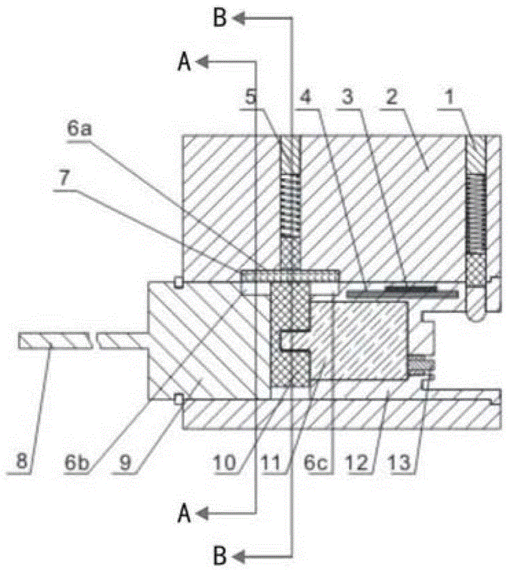
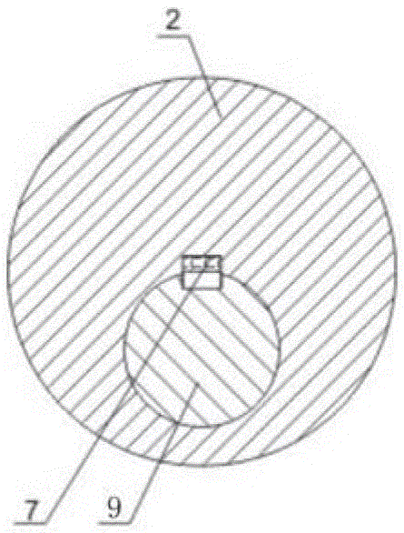
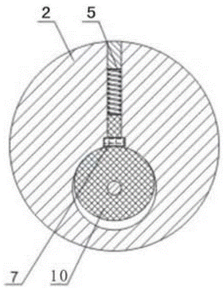
[0037] like figure 1 , figure 2 and image 3 As shown, the micro-power consumption simple clutch electronic lock head of the present invention includes a lock head body 2 and a lock head core placed in the lock head body 2, and the lock head core includes a front section 12 of a lock head core independent of each other and a rear end of the lock head core. Section 9, a circuit board 4 with at least one key partition and a micromotor 11 electrically connected to the circuit board 4 are installed in the front section 12 of the lock core, and a CPU3 is installed on the circuit board 4, and the front section 12 of the lock core is used for inserting One end of the electronic key ( figure 1 The right end of the center) is provided with a contact 13 for contacting and connecting with the electronic key, the inner end of the contact 13 is electrically connected with the circuit board 4, and the connecting line includes a power line and a communication line; the inner wall of the l...

Embodiment 2

[0046] Compared with Embodiment 1, this embodiment adds the structure that the eccentric cam 10 only turns half a circle (forward rotation and reverse rotation are both half circles), and other structures are completely the same.

[0047] like Figure 7 and Figure 8 As shown, the front section 12 of the lock core is provided with a semicircular annular groove 18, and the eccentric cam 10 is provided with a boss 17, and the boss 17 is placed in the semicircular annular groove 18 and can be positioned in the entire semicircular annular groove 18. slide inside.

[0048] like Figure 8 and Figure 10 As shown, the two static states of the protruding post 17 in the semicircular annular groove 18 are respectively at the two ends of the semicircular annular groove 18 .

[0049] like Figure 7 and Figure 8 As shown, in the locked state, the left end of the boss 17 is placed in the semicircular annular groove 18; Figure 9 and Figure 10 , during the conversion process from t...


PUM


Abstract

The invention discloses a simple clutch electronic lock head with low power consumption. A driver is installed in the lock core, and the inner wall of the lock body is provided with a clutch cavity for the lock body. The clutch connection key is placed in the lock body clutch cavity. A spring push rod is arranged in the lock body; the lock core includes a front part of the lock core and a rear part of the lock core, one end of the front part of the lock core is used for inserting an electronic key, and a A reciprocating device connected with the driver and used to push the clutch connection key into the clutch cavity of the lock body. The front section of the lock core and the rear section of the lock core are respectively provided with a clutch cavity in the front section of the lock core corresponding to the clutch cavity of the lock body and the rear clutch cavity of the lock core, the spring push rod is used to push the clutch connection key into the front clutch cavity of the lock core and the rear clutch cavity of the lock core. The invention realizes the opening and closing through the cooperation of the clutch connection key and the clutch cavity, and separates the front and rear sections of the lock core, so that the front section will not drive the rear section to rotate when locking, which significantly enhances the violence resistance.

Description

technical field [0001] The invention relates to an intelligent electronic lock head, in particular to a simple clutch electronic lock head with low power consumption that separates the front and rear sections of the lock cylinder. Background technique [0002] At present, both mechanical locks and electronic locks are widely used in the market, and electronic locks are welcomed by more and more users because of their reliable safety performance. In the field of security technology prevention, electronic locks with anti-theft alarm function replace traditional mechanical combination locks, which overcome the shortcomings of mechanical combination locks with few passwords and poor safety performance, and make combination locks more effective both in technology and in performance. All have been greatly improved. [0003] In the current electronic lock industry, the most advanced technology is the micro-power electronic lock technology. The applicant has applied for a patent o...

Claims


Application Information

Patent Timeline
Patent Type & Authority Patents(China)
IPC IPC(8): E05B47/00E05B15/00
Inventor 喇晓路周国权
Owner CHENGDU HIZIMA TECH CO LTD
Learn More