Micro power consumption simple intelligent electronic lock head
An electronic lock head and micro-power consumption technology, which is applied in building locks, locks controlled by non-mechanical transmission, buildings, etc., can solve the problem of insufficient realization of the transmission structure and achieve low power consumption, improved safety level, and low current Effect
- Summary
- Abstract
- Description
- Claims
- Application Information
AI Technical Summary
Problems solved by technology
Method used
Image
Examples
Embodiment 1
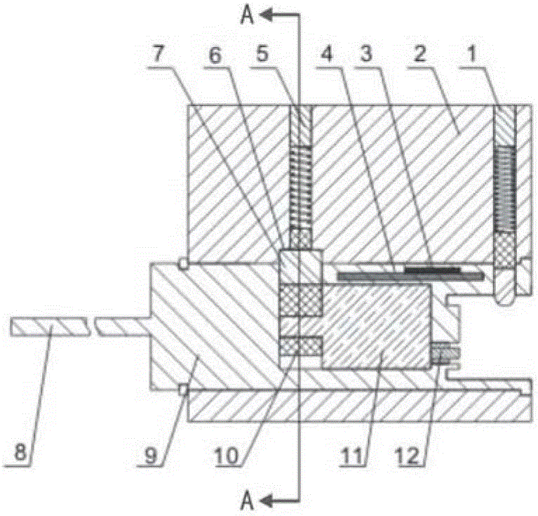
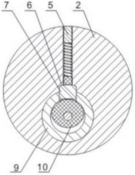
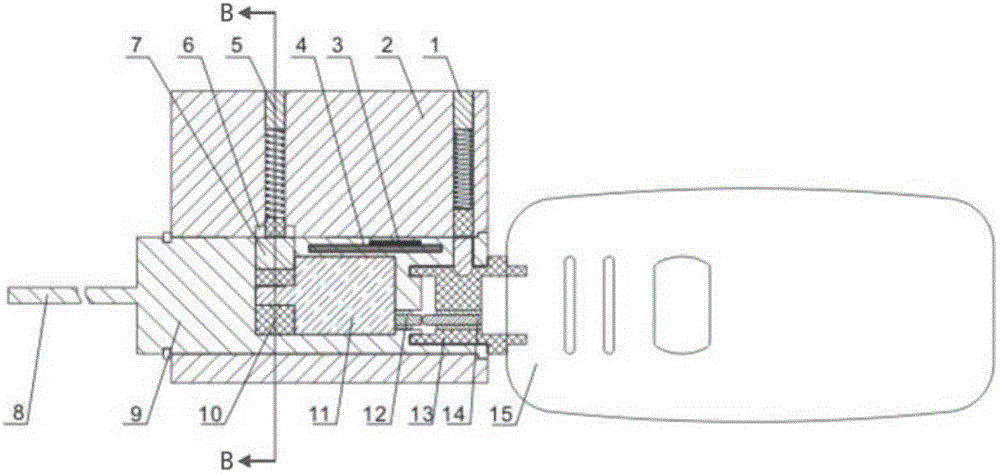
[0035] Such as figure 1 and figure 2 As shown, the micro-power consumption simple intelligent electronic lock head of the present invention includes a lock head body 2 and a lock head core 9 placed in the lock head body 2, and a circuit board with at least one key partition is installed in the lock head core 9 4 and the micromotor 11 that is electrically connected with the circuit board 4, CPU 3 is installed on the circuit board 4, and the end of the lock core 9 for inserting the electronic key is provided with a contact 12 for contacting and connecting with the electronic key, and the contact 12 of the contact 12 The inner end is electrically connected with the circuit board 4, and its connection line includes a power line and a communication line; the inner wall of the lock head body 1 is provided with a block cavity 6 for limiting the block 7, and the block 7 is in the lock. When the head is in the locked state, its two ends are respectively located in the block cavity 6 ...
Embodiment 2
[0043] Compared with Embodiment 1, this embodiment adds the structure that the eccentric cam 10 only turns half a circle (forward rotation and reverse rotation are both half circles), and other structures are completely the same.
[0044] Such as Figure 5 and Figure 6 As shown, the lock head core 9 is provided with a semicircular annular groove 17, and the eccentric cam 10 is provided with a boss 16, and the boss 16 is placed in the semicircular annular groove 17 and can be placed in the semicircular annular groove 17 slide.
[0045] Such as Figure 6 and Figure 8 As shown, the two static states of the protruding post 16 in the semicircular annular groove 17 are respectively at the two ends of the semicircular annular groove 17 .
[0046] Such as Figure 5 and Figure 6 As shown, in the locked state, the upper end of the boss 16 is placed in the semicircular annular groove 17; Figure 7 and Figure 8 , during the conversion process from the locked state to the unloc...
PUM
 Abstract
Description
Claims
Application Information
 - R&D
- Intellectual Property
- Life Sciences
- Materials
- Tech Scout
- Unparalleled Data Quality
- Higher Quality Content
- 60% Fewer Hallucinations
Browse by: Latest US Patents, China's latest patents, Technical Efficacy Thesaurus, Application Domain, Technology Topic, Popular Technical Reports.
© 2025 PatSnap. All rights reserved.Legal|Privacy policy|Modern Slavery Act Transparency Statement|Sitemap|About US| Contact US: help@patsnap.com


