Method and equipment for calibrating fighter weapon system by fiber-optic gyroscope

A fiber optic gyroscope and fiber optic gyroscope technology, which is applied in the field of weapon calibration, can solve problems such as low efficiency, unguaranteed target calibration accuracy, and inability to meet target calibration at any time.

Active Publication Date: 2014-10-08
陈远春 +2
View PDF5 Cites 11 Cited by
  • Summary
  • Abstract
  • Description
  • Claims
  • Application Information

AI Technical Summary

Problems solved by technology

The existing main calibration method is the reduced-distance target calibration method. Before target calibration, more than a dozen people must first coordinate the attitude of the top-level body, using the horizontal plane as a reference, and then use the wire-drawing method to determine the body position. During the entire weapon calibration process, the body position Both the measurement process and the target calibration process have the disadvantages of complex and cumbersome steps, low efficiency, and the need for a large number of people to work together, resulting in at least 3 to 4 hours for each calibration, which cannot meet the requirements of modern warfare for the rapid response of fighters. Easily affected by various natural factors such as terrain and wind, the accuracy of target calibration cannot be guaranteed, and it cannot meet the needs of target calibration at any time in the field environment

Method used


Image

  • Method and equipment for calibrating fighter weapon system by fiber-optic gyroscope
  • Method and equipment for calibrating fighter weapon system by fiber-optic gyroscope
  • Method and equipment for calibrating fighter weapon system by fiber-optic gyroscope

Examples


Embodiment 1

[0047] When it is necessary to calibrate the head-up display in the fighter weapon system, the following methods are used for calibration:

[0048] A method for calibrating the head-up display of a fighter plane using an optical fiber gyroscope according to the present invention comprises the following steps:

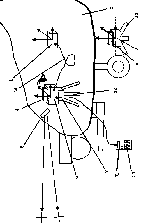
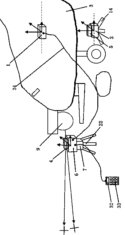
[0049] ① Install the first fiber optic gyro module 1 on the fighter body 3, the first fiber optic gyro module 1 includes three fiber optic gyroscopes and corresponding integral calculation modules arranged in the directions of three mutually perpendicular space coordinate axes of x, y, and z, The angular velocity information measured by the three fiber optic gyroscopes is integrated through the integral calculation module to obtain the angle data of the three axis directions of the current first fiber optic gyroscope module 1;

[0050] ②Place the body longitudinal axis orientation determination device 2 under the body 3, measure the orientation and posture of the body 3...

Embodiment 2

[0066] When it is necessary to calibrate the photoelectric stabilized sight in the fighter weapon system, the following methods are used for calibration:

[0067] A method for calibrating the photoelectric stabilization of fighter jets using a fiber optic gyroscope according to the present invention comprises the following steps:

[0068] ① Install the first fiber optic gyro module 1 on the fighter body 3. The first fiber optic gyro module 1 is composed of three fiber optic gyroscopes and corresponding integral calculation modules arranged in the directions of three mutually perpendicular space coordinate axes of x, y, and z , the angular velocity information measured by the three fiber optic gyroscopes is integrated through the integral calculation module to obtain the angle data of the three axis directions of the current first fiber optic gyroscope module 1;

[0069] ②Place the body longitudinal axis orientation determination device 2 under the body 3, measure the orientati...

Embodiment 3

[0082] When it is determined that the direction of the HUD line of sight is correct, the aircraft gun in the fighter weapon system needs to be calibrated, and the following method is used for calibration:

[0083] A method for calibrating fighter aircraft guns using an optical fiber gyroscope according to the present invention comprises the following steps:

[0084] ① Install the first fiber optic gyro module 1 on the fighter body 3. The first fiber optic gyro module 1 is composed of three fiber optic gyroscopes and corresponding integral calculation modules arranged in the directions of three mutually perpendicular space coordinate axes of x, y, and z , the angular velocity information measured by the three fiber optic gyroscopes is integrated through the integral calculation module to obtain the angle data of the three axis directions of the current first fiber optic gyroscope module 1;

[0085] ② Place the azimuth and attitude determination instrument directly behind the he...


PUM


Abstract

The invention provides a method and equipment for calibrating a fighter weapon system by a fiber-optic gyroscope. The equipment comprises an azimuth and posture determining instrument and fighter vertical axis azimuth determining equipment, wherein the azimuth and posture determining instrument comprises an azimuth and posture regulator, a second fiber-optic gyroscope module is mounted on the azimuth and posture regulator, a computer for analyzing azimuth angle data is embedded into the second fiber-optic gyroscope module, an electronic optical aligner and a display are mounted on the second fiber-optic gyroscope module, both an integral solving module of the second fiber-optic gyroscope module and the display are connected with the computer through data transmission interfaces, the computer is connected with an integral solving module of a first fiber-optic gyroscope module through a data transmission interface, and the fighter vertical axis azimuth determining equipment can measure the current vertical axis direction of the fighter and indicate the direction through a cross line of sight, displayed in a level eyepiece. The method and the equipment have the advantages that steps in the process for calibrating fighter weapons can be effectively simplified, the calibrating efficiency can be effectively improved and the affect of natural factors can be prevented.

Description

technical field [0001] The invention relates to a weapon calibration method and equipment, in particular to a method and equipment for calibrating a fighter jet weapon system by using an optical fiber gyroscope. Background technique [0002] Weapon systems used on gunships and fixed-wing fighter aircraft require calibration before use, after weapons are changed, or when the pilot has doubts about their accuracy. The existing main calibration method is the reduced-distance target calibration method. Before target calibration, more than a dozen people must first coordinate the attitude of the top-level body, using the horizontal plane as a reference, and then use the wire-drawing method to determine the body position. During the entire weapon calibration process, the body position Both the measurement process and the target calibration process have the disadvantages of complex and cumbersome steps, low efficiency, and the need for a large number of people to work together, re...

Claims


Application Information

Patent Timeline
Patent Type & Authority Applications(China)
IPC IPC(8): F41G3/00G01C19/02
Inventor 焦锋利李平金陈远春
Owner 陈远春
Why Eureka
Try Eureka