Spherical video image correction method

A technology of video image and correction method, applied in the field of video processing, can solve the problems of cumbersome video image correction process, and achieve the effect of real-time correction processing, enhanced reusability, good maintainability and compatibility

Active Publication Date: 2021-01-15
CHENGDU CHENGDIAN GUANGXIN TECH
View PDF14 Cites 7 Cited by
  • Summary
  • Abstract
  • Description
  • Claims
  • Application Information

AI Technical Summary

Problems solved by technology

However, the video image correction process of this method is cumbersome. First, image acquisition is required before correction, that is, the image projected by each projector is taken by a digital camera, and then the acquired image is processed and matrix transforma

Method used


Image

  • Spherical video image correction method

Examples


Embodiment 1

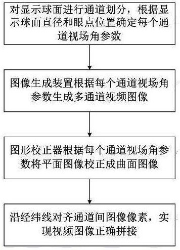
[0044] see figure 1 , a spherical video image correction method, comprising the following steps:

[0045] a. Set LED lamp beads to be arranged on the inner surface along the spherical longitude and latitude to form a display surface, and be divided into multiple display channels along the longitude and latitude, the pole area is divided into separate display channels along the latitude, and the spherical display surface is divided into side channels and top or bottom Channel, according to the diameter of the display sphere and the position of the eye point to determine the display field of view parameters of each channel;

[0046] b. The video image generation device generates multi-channel rectangular graphics according to the display field angle parameters, and synchronously outputs them to the back-end graphics corrector for geometric correction of graphics from plane to spherical surface;

[0047] c. The graphics corrector converts each channel image generated by the vide...

Embodiment 2

[0052] see figure 1 , a spherical video image correction method, comprising the following steps:

[0053] a. Set LED lamp beads to be arranged on the inner surface along the spherical longitude and latitude to form a display surface, and be divided into multiple display channels along the longitude and latitude, the pole area is divided into separate display channels along the latitude, and the spherical display surface is divided into side channels and top or bottom Channel, according to the diameter of the display sphere and the position of the eye point to determine the display field of view parameters of each channel;

[0054] b. The video image generation device generates multi-channel rectangular graphics according to the display field angle parameters, and synchronously outputs them to the back-end graphics corrector for geometric correction of graphics from plane to spherical surface;

[0055] c. The graphics corrector converts each channel image generated by the vide...

Embodiment 3

[0069] see figure 1 , a spherical video image correction method, comprising the following steps:

[0070] a. Set LED lamp beads to be arranged on the inner surface along the spherical longitude and latitude to form a display surface, and be divided into multiple display channels along the longitude and latitude, the pole area is divided into separate display channels along the latitude, and the spherical display surface is divided into side channels and top or bottom Channel, according to the diameter of the display sphere and the position of the eye point to determine the display field of view parameters of each channel;

[0071] b. The video image generation device generates multi-channel rectangular graphics according to the display field angle parameters, and synchronously outputs them to the back-end graphics corrector for geometric correction of graphics from plane to spherical surface;

[0072] c. The graphics corrector converts each channel image generated by the vide...


PUM


Abstract

The invention discloses a spherical video image correction method, which belongs to the technical field of video processing, and is characterized by comprising the following steps of: a, determining adisplay field angle parameter of each channel; b, generating a multi-channel rectangular graph, and synchronously outputting the multi-channel rectangular graph to a rear-end graph corrector for geometric correction of the graph from a plane to a spherical surface; c, converting each channel image into a curved surface image by the graph corrector; d, storing the graphic correction parameters inFLASH; and e, projecting the pre-deformed image onto a hemispherical projection screen by the projector model for presenting a real target image. Geometric transformation from a plane image to a spherical image can be achieved by loading the parameters through hardware electrification, and image acquisition, grid correction, feature point acquisition and calculation of a limited display area are not needed; effective pixels of a video image are fully utilized, real-time correction processing of the video image is achieved, reusability of parameters between channels is enhanced, and secondary correction of later maintenance is avoided.

Description

technical field [0001] The invention relates to the technical field of video processing, in particular to a spherical video image correction method. Background technique [0002] Immersive dome displays all use projection display technology. Multiple projectors use image splicing and fusion to realize the dome display function. On the one hand, it is difficult to achieve full-field display in this way, especially in real image display systems. Because once an observer or object is inside the system, it will block part of the display area; on the other hand, in addition to image geometric correction, this display method also needs image stitching and image fusion. Due to the large stitching and fusion area, The actual pixel utilization per projector is very small. [0003] In order to solve many problems of projectors such as small field of view, low contrast, short lifespan, high price and difficult maintenance, the LED visual spherical screen display scheme is proposed, wh...

Claims


Application Information

Patent Timeline
IPC IPC(8): G06T5/00H04N9/31
CPCG06T5/006H04N9/3185
Inventor 解军王继岷贺卫东曾一雄王万勤
Owner CHENGDU CHENGDIAN GUANGXIN TECH
Why Eureka
Try Eureka