Conductive Rod Assembly Tooling

A technology for assembling tooling and conductive rods, which is applied in the direction of cable laying equipment, etc., can solve problems such as scratches, increase use costs, and reduce the centering and positioning accuracy of conductive rods, so as to improve positioning accuracy, reduce costs, and ensure assembly quality.

Inactive Publication Date: 2017-02-01
STATE GRID CORP OF CHINA +1
View PDF10 Cites 0 Cited by
  • Summary
  • Abstract
  • Description
  • Claims
  • Application Information

AI Technical Summary

Problems solved by technology

When the conductive rod is installed in the porcelain casing of this length, there is a phenomenon that the conductive rod "bows its head", and there are two general solutions: one method is to directly add a sheath made of flexible material to the end of the conductive rod , use the sheath to contact the inner wall of the casing. Although the structure of the sheath is simple in this method, there is a large friction between the sheath and the porcelain casing. When the sheath moves with the conductive rod, the end of the conductive rod The part is often exposed from the sheath, so that the protection of the sheath to the conductive rod is not in place, so that the end of the conductive rod will directly contact the inner wall of the porcelain sleeve, and eventually cause the inner wall of the porcelain sleeve to be scratched; another method It is to use a small pulley to support the conductive rod inside the casing to prevent the end of the conductive rod from colliding with the inner wall of the casing. Although this method is simple, the small pulley can only prevent the end of the conductive rod from colliding with the porcelain when in use. The inner wall of the casing cannot help the centering and positioning of the conductive rod, and other means are needed to assist centering and positioning in subsequent use, which increases the labor intensity of the conductive rod assembly
[0003] The Chinese utility model patent whose notification number is CN202363840U discloses a kind of guide car for GIS three-phase common box busbar conductive rod tooling. The positioning plate is coaxially fixed by the connecting rod extending from front to back. On the guiding pole and the positioning plate, there is a conductive rod hole for the conductive rod to be installed to pass through. Several small holes are evenly distributed on the hole wall of the conductive rod hole. There are several large rollers on the outer circumference of the guide pole. Through the large rollers, the guide pole slides coaxially into the busbar tube to ensure that the guide pole and the conductive rod hole on the positioning plate are in line with the disc insulator on the busbar barrel. The contact seat is opposite, but because the conductive rod hole for the conductive rod to be installed is fixed on the guide pole and the positioning plate, this limits that a set of guide vehicles can only be used for diameters and through holes. When the diameter of the conductive rod is smaller than the diameter of the through hole, although the conductive rod can be fixed by adding fillers in the through hole, this will greatly reduce the centering accuracy of the conductive rod. In order to be suitable for the assembly of conductive rods with different diameters, manufacturing multiple sets of guide vehicles increases the cost of use

Method used


Image

  • Conductive Rod Assembly Tooling
  • Conductive Rod Assembly Tooling
  • Conductive Rod Assembly Tooling

Examples


Embodiment Construction

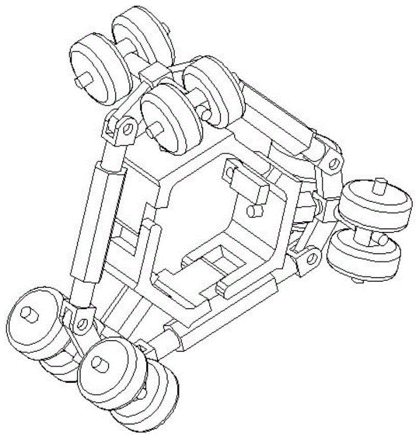
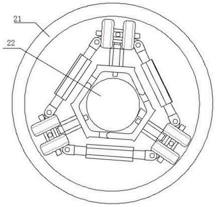
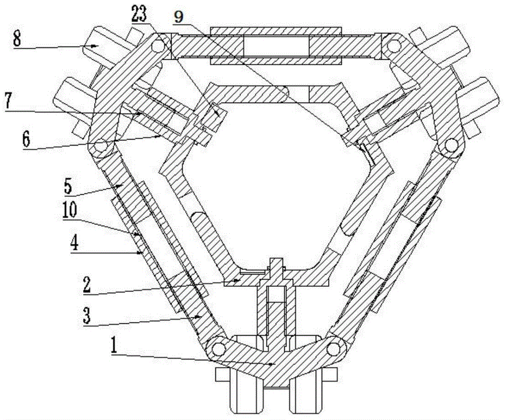
[0029] Embodiment 1 of a conductive rod assembly tooling of the present invention: as figure 1 As shown in -9, it includes three support frames 1 evenly distributed on a circumference, the center of the circle where the three support frames 1 are located coincides with the axis of the installed pipe 21, and two adjacent support frames 1 are connected through an adjustable connection mechanism Connect with each other and form a ring-shaped outer frame. Three support frames 1 are connected with rollers 8 for contacting the inner wall of the installed pipe 21 at one end outside the ring-shaped outer frame. Three support frames 1 are connected at one end inside the ring-shaped outer frame. A supporting plate 2 for contacting with and positioning the conductive rod 22 installed in the center of the installed pipe 21 is connected.

[0030] The support frame 1 includes a threaded column 16 for connecting with the supporting plate 2, the threaded column 16 extends in the radial direct...


PUM


Abstract

The invention discloses a conducting rod assembling tool which comprises three supporting frames evenly distributed on a circumference. The every two adjacent supporting frames are connected, an annular framework is formed through connection, the end, on the outer side of the annular framework, of each supporting frame is provided with a wheel in contact with the inner wall of a mounted tube, the end, on the inner side of the annular framework, of each supporting frame is provided with a supporting plate which is in contact with a conducting rod mounted in the center of the mounted tube and is used for locating the conducting rod, and the supporting plates are connected with the supporting frames in a distance adjustable mode through spiral adjusting mechanisms. According to the conducting rod assembling tool, the distances between the three supporting plates are adjustable, the space defined by the three supporting plates can be large or small, and the conducting rod assembling tool is suitable for assembling conducting rods of bus tubes of different diameters.

Description

technical field [0001] The invention relates to the field of assembly of high-voltage, ultra-high-voltage, and ultra-high-voltage pipeline busbars, in particular to a process device for installing inlet and outlet bushings and conducting rods in pipeline busbars. Background technique [0002] At present, as the voltage level of high-voltage electrical equipment increases, the creepage distance and insulation distance of the incoming and outgoing porcelain bushings (composite bushings) also increase, and the diameter and length of the corresponding porcelain bushings also increase. The diameter of the million-volt incoming and outgoing porcelain bushing is more than one meter, and the length is more than ten meters long. When the conductive rod is installed in the porcelain casing of this length, there is a phenomenon that the conductive rod "bows its head", and there are two general solutions: one method is to directly add a sheath made of flexible material to the end of the...

Claims


Application Information

Patent Timeline
Patent Type & Authority Patents(China)
IPC IPC(8): H02G1/08
Inventor 林麟汪宁阎关星周华姚锋娟王向克姬秋红周跃刚程建强都基峰
Owner STATE GRID CORP OF CHINA
Why Eureka
Try Eureka