A fast centering positioning clamping device for u-shaped thin-walled rotary parts

A thin-walled rotary and clamping device technology, applied in the direction of grinding workpiece supports, etc., can solve the problems of difficulty in guaranteeing workpiece rotation accuracy, uneven polishing surface accuracy, lack of centering and positioning mechanism, etc., and achieves easy popularization and wide application range. , the effect of simple structure

Active Publication Date: 2017-10-20
GUANGDONG UNIV OF TECH
View PDF9 Cites 0 Cited by
  • Summary
  • Abstract
  • Description
  • Claims
  • Application Information

AI Technical Summary

Problems solved by technology

[0004] The current clamping method for U-shaped rotary thin-walled parts is manual loading and unloading, alignment and vacuum suction clamping. The workpiece is manually placed on the rotatable vacuum suction spindle with the jacket or mandrel as a reference, and the U-shaped product is clamped by negative air pressure. Absorption at the bottom of the workpiece, lack of precise centering and positioning mechanism, severe eccentricity, difficulty in ensuring the rotation accuracy of the workpiece, resulting in unstable polishing process, uneven polishing surface accuracy, rework, and reduced processing efficiency.

Method used


Image

  • A fast centering positioning clamping device for u-shaped thin-walled rotary parts
  • A fast centering positioning clamping device for u-shaped thin-walled rotary parts
  • A fast centering positioning clamping device for u-shaped thin-walled rotary parts

Examples


Embodiment 1

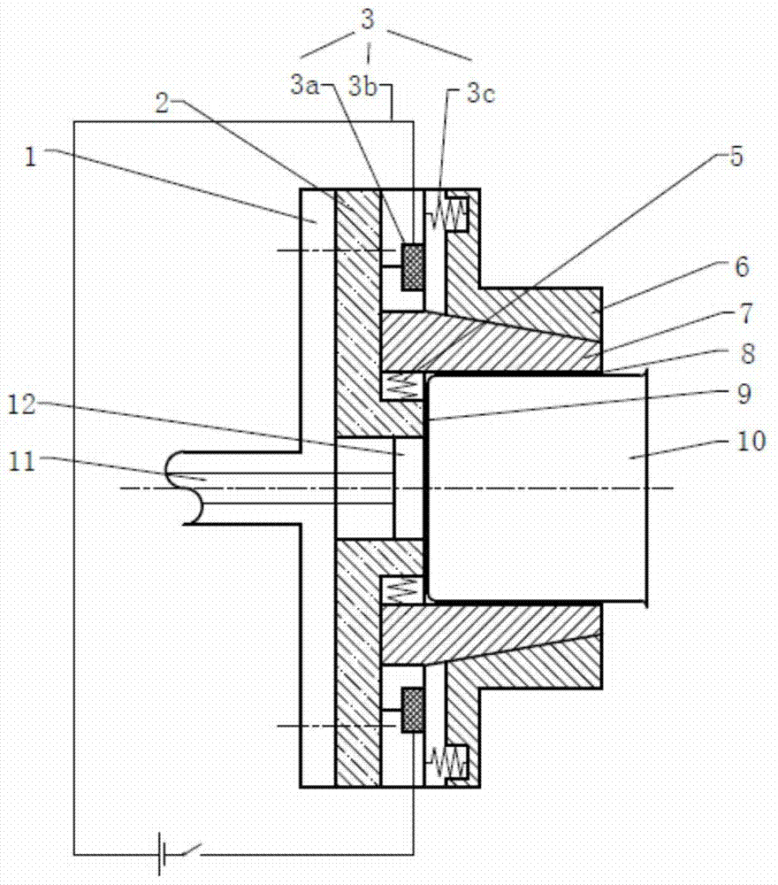
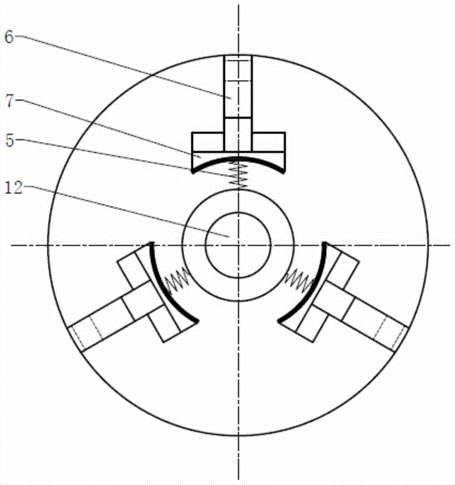
[0028] Such as Figure 1 to Figure 3 As shown, a U-shaped thin-walled rotary fast centering positioning clamping device includes a hollow rotary spindle 1, a spindle flange 2, a radially moving wedge 7, an axially moving wedge 6, and a radial reset member 5 and an axial drive mechanism 3; the hollow rotary spindle 1 has a built-in vacuum suction tube 12, one end of which is connected to a vacuum suction cup 12 to generate an attractive force to suck the bottom surface of the U-shaped thin-walled rotary member 10; the spindle flange 2 is fixed on the hollow rotary On the end of the main shaft 1, the radially moving wedge 7 is radially connected to the main shaft flange 2 through the radial reset member 5, and the axially moving wedge 6 is passed through the axial driving mechanism 3 It is axially connected with the main shaft flange, and the radially moving wedge 7 is slidingly fitted with the axially moving wedge 6; the axially moving wedge 6 is driven by the axial driving mec...

Embodiment 2

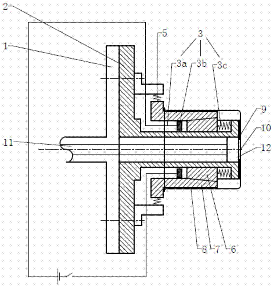
[0037] Such as Figure 4 As shown, compared with Embodiment 1, the main difference is that the axial drive mechanism is driven by the cylinder 4 or driven by an electronic push rod. Its working principle is basically the same as that of Embodiment 1, and will not be repeated here.


PUM


Abstract

The invention provides a quick centering, positioning and clamping device of a U-shaped thin-walled rotating member. The quick centering, positioning and clamping device comprises a hollow rotating main shaft, a main shaft flange, radial moving wedges and axial moving wedges, wherein a vacuum straw is arranged in the hollow rotating main shaft, and one end of the vacuum straw is connected with a vacuum sucking disc, so as to generate suction force to suck the bottom surface of the U-shaped thin-walled rotating member; the main shaft flange is fixed to the end of the hollow rotating main shaft, the radial moving wedges are radially connected with the main shaft flange by virtue of radial reset members, the axial moving wedges are axially connected with the main shaft flange by virtue of an axial driving mechanism, and the radial moving wedges are in sliding fit with the axial moving wedges; the axial moving wedges are driven to move along the axial direction by the axial driving mechanism, and the radial moving wedges are driven to move along the radial direction by the axial moving wedges and are driven to reset by the radial reset members. According to the quick centering, positioning and clamping device, the U-shaped thin-walled rotating member can be clamped, so that the U-shaped thin-walled rotating member can be quickly and accurately centered in any state, the rotating accuracy is high, the clamping is realized without deformation, and the surface machining accuracy is effectively increased.

Description

technical field [0001] The invention relates to a clamp, in particular to a fast centering positioning and clamping device for a U-shaped thin-walled rotary part. Background technique [0002] With the development of modern society and the improvement of people's quality of life, the demand and variety of products with U-shaped rotary thin-walled parts are increasing, and the requirements for surface processing quality are getting higher and higher, and the surface of the product is required to be smooth and uniform. Non-scratch processing effect, for metal products, it is required to form a shiny metallic luster. The surface processing of metal products is a labor-intensive job with mild dust pollution. Due to the rising labor costs, environmental protection and labor protection needs, it is increasingly dependent on robot-automated surface grinding and polishing processing to meet the requirements. [0003] The current processing technology of U-shaped rotary thin-walled ...

Claims


Application Information

Patent Timeline
Patent Type & Authority Patents(China)
IPC IPC(8): B24B41/06
CPCB24B41/061
Inventor 阎秋生梁华卓高伟强
Owner GUANGDONG UNIV OF TECH
Why Eureka
Try Eureka